Sharp LL-T2010W (serv.man13) Service Manual ▷ View online
LL-T2010W
CONNECTION, ADJUSTMENT, OPERATION, AND FUNCTIONS
2 – 5
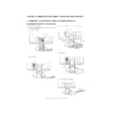
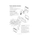
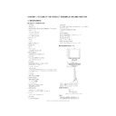
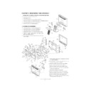
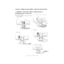
2. INSTRUCTIONS FOR ATTACHING A VESA COMPLIANT ARM
An arm or stand based on the VESA standard (commercially available)
can be attached to the monitor.
Procurement of the arm or stand is at the customer’s discretion.
Arms or stands able to be used
Attachments must satisfy the following.
• Compatible with the VESA standard.
• Have a gap of 100 mm x 100 mm between the screw holes on the
section to be attached.
• Not be likely to fall off or break off after being attached to the monitor.
How to attach the arm or stand
Caution: Be careful not to cut or jam your fingers.
Notes:
• Do not overly bend the cable or add extension cords as this could
lead to malfunction.
• While following these instructions, please also refer to the installa-
tion instructions in the operation manual included with the arm or
stand.
stand.
1.
Spread out a soft cloth on a suitable horizontal surface.
2.
Being careful not to damage the monitor, gently lay the monitor on it
display-side down.
3.
Remove the stand cover.
4. Remove the two screws, and remove the cover.
5. Remove the four screws and then remove the stand from the moni-
tor.
6. Attach the arm to the monitor with the four screws.
Note: The screws used to attach the arm should be M4 screws with a
length of 8 mm ~ 10 mm protruding from the surface to be attached.
Using different screws could lead to malfunction or may lead to the
monitor falling off, internal damaged, personal injury.
monitor falling off, internal damaged, personal injury.
(Rear View)
Stand cover
Lift one side
Cover
Two screws
Four screws
Stand
Four screws
8
10mm
Screw used to attach arm
Arm
Part of monitor to which arm is
attached
attached
LL-T2010W
CONNECTION, ADJUSTMENT, OPERATION, AND FUNCTIONS
2 – 6
3. ADJUSTMENT
3-1. ADJUSTMENT METHOD
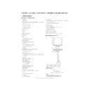
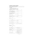
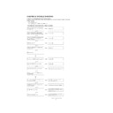
6) Version display (for service)
Power ON
Display the software version.
Press the above two buttons at same time, and while turn the power on.
Press the above two buttons at same time, and while turn the power on.
7) Aging (for service)
Power
ON
Red
3
Green
3
Blue
3
Yellow
3
Purple
3
Light Blue
3
White
3
Black
When the test is terminate, Power off.
LL-T2010W
VERSION 1.00
2002. 2. 14
CHECKSUM XXXX
MENU
SELECT
MENU
MENU
1) Adjusting the backlight
Buttons
3) Resetting all adjustment values
Power ON
Power ON
Press the above two buttons at same time, and while turn the power on.
2) ADJUSTMENT menu reset
Press the two buttons at same time.
4) Adjustment lock function (Look and release)
While pressing the MENU button, turn the power on.
5) Automatic screen adjustment
MENU
ADJUSTMENT
AUTO
SELECT
CLOCK
SELECT
PHASE
SELECT
H-POS
SELECT
V-POS
MENU
GAIN
CONTROL
CONTROL
AUTO
SELECT
BLACK LEVEL
SELECT
CONTRAST
MENU
COLOR
CONTROL
CONTROL
COLOR MODE (sRGB, COOL STD WARM USER)
SELECT
R-CONTRAST
SELECT
SELECT
G-CONTRAST
B-CONTRAST
MENU
MODE SELECT
OSD H-POSITION
SELECT
OSD V-POSITION
SELECT
EXPAND
SELECT
SCALING
SELECT
LANGUAGE
MENU
MENU
(for ANALOG)
buttons
buttons
buttons
buttons
buttons
buttons
buttons
buttons
buttons
buttons
buttons
buttons
buttons
buttons
SELECT
400 LINES
buttons
buttons
SELECT buttons
END
MENU
SELECT
SELECT
LL-T2010W
CONNECTION, ADJUSTMENT, OPERATION, AND FUNCTIONS
2 – 7
3-2. ADJUSTMENT ITEM LIST
BUTTON
ITEM
ADJUSTMENT
DESCRIPTION
MENU
MENU 1:
ADJUSTMENT
ADJUSTMENT
MANUAL
CLOCK
0~255
CLOCK: The figure below demonstrates how to adjust
so that vertical flicker noise is not emitted.
(
(
e d
buttons)
MENU 1
4
MENU 2
4
MENU 3
4
MENU 4
4
MENU END
PHASE
0~31
PHASE:
The figure below demonstrates how to adjust
so that horizontal flicker noise is not emitted.
(
so that horizontal flicker noise is not emitted.
(
e d
e d
e d
e d
buttons)
H-POS
0~
H-POS (horizontal positioning) and
V-POS (vertical positioning)
V-POS (vertical positioning)
To center the screen image within the boundaries of the
screen, adjust the left-right (H-POS) values and the up-
down (V-POS) values. (
screen, adjust the left-right (H-POS) values and the up-
down (V-POS) values. (
e d
e d
e d
e d
buttons)
V-POS
0~
AUTO
Automatic screen adjustment
Options in the ADJUSTMENT Menu can be adjusted
automatically
(CLOCK, PHASE, H-POS V-POS).
automatically
(CLOCK, PHASE, H-POS V-POS).
MENU 2:
GAIN CONTROL
GAIN CONTROL
MANUAL
BLACK LEVEL
0~127
BLACK LEVEL: Total screen brightness can be adjusted
while watching the color pattern.
(
(
e d
buttons)
CONTRAST
0~127
CONTRAST:
While watching the color pattern, adjust-
ments can be made so that all gradua-
tions appear. (
ments can be made so that all gradua-
tions appear. (
e d
e d
e d
e d
buttons)
AUTO
GAIN CONTROL Menu
AUTO:
AUTO:
Every menu option is automatically adjusted
using the Auto Gain Control function.
using the Auto Gain Control function.
MENU 3:
COLOR CONTROL
COLOR CONTROL
COLOR MODE
sRGB,
COOL • STD • WARM
(5 levels),
USER R • G • B: 0~100
COOL • STD • WARM
(5 levels),
USER R • G • B: 0~100
sRGB: sRGB is international standard of color represen-
tation specified by IEC (International Electrotechni-
cal Commission). Color conversion is made in
taking account of liquid crystals characteristics and
represents color tone close to it original image.
cal Commission). Color conversion is made in
taking account of liquid crystals characteristics and
represents color tone close to it original image.
COOL
: Color tone bluer than standard
•
: Color tone slightly bluer than standard
STD
: Color tone standard setting
•
: Color tone slightly redder than standard
WARM
: Color tone redder than standard
USER
R-CONTRAST
:
e
button for blue-green
d
button for red
G-CONTRAST :
e
button for purple
d
button for green
B-CONTRAST
:
e
button for yellow
d
button for blue
MENU 4:
MODE SELECT
MODE SELECT
OSD H-POSITION
OSD H-POSITION (OSD horizontal position)
The position of the OSD display can be moved to the
left and right. (
left and right. (
e d
buttons)
OSD V-POSITION
OSD V-POSITION (OSD vertical position)
The position of the OSD display can be moved up and
down. (
down. (
e d
buttons)
400 LINES
640 • 720
400 LINES (degree of resolution)
You can specify the horizontal resolution of a 400-line
screen when using US text, etc.
(
screen when using US text, etc.
(
e d
buttons)
640: 640
u
400 dot mode
720: 720
u
400 dot mode (US text etc.)
EXPAND
OFF, ON1, ON2
For display modes of less than 1600 x 1200 pixels, the
display can be expanded if desired. (
display can be expanded if desired. (
e d
buttons)
OFF: Expansion off
ON1: Using the fixed aspect ratio, the entire screen is
ON1: Using the fixed aspect ratio, the entire screen is
enlarged.
ON2: The entire screen is enlarged.
SCALING
1~5
SCALING (Level of scaling)
The sharpness of the image can be adjusted.
(
(
e d
buttons)
LANGUAGE
7 countrys
DEUTSCH, ENGLISH,
ESPANOL, FRANCAIS,
ITALIANO, NETHER-
LAND, SVENSKA
DEUTSCH, ENGLISH,
ESPANOL, FRANCAIS,
ITALIANO, NETHER-
LAND, SVENSKA
LANGUAGE
Messages displayed on the screen and OSD Menu con-
tents can be changed to the following languages.
tents can be changed to the following languages.
Dutch, English, French, German, Spanish, Italian,
Swedish.
Swedish.
SELECT
Select the item
< >
0~31
Adjusting the backlight
POWER OFF
Display

