Sharp UP-X500 (serv.man5) Service Manual ▷ View online
UP-X500I
Fixing the HDD unit
– 3 –
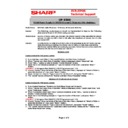
5. Fixing the HDD unit
5-1. Assembly HDD unit
Attach the holder
1
to the angle
2
, and fix the assembly
to the HDD
5
with the screw
3
. Connect the connector
4
to the HDD
5
. (Be careful of the direction.)
Caution: All the parts are packed together with the set as accessories.
5-2. Fixing the HDD unit
Remove the screw
1
and remove the HDD cover
2
. Dis-
connect the connector
5
and install the HDD unit
3
with
the screw
4
.
Caution: The screw
4
is packed with the set as an accessory.
6. Removing the AC cord
Remove the screw
1
, and remove the AC cord cover
2
.
Remove the screws
3
, and remove the AC cover
4
.
Disconnect the connector and remove the earth cable
5
and the AC cord.
Caution: Disconnect the power plug from the power outlet before work.
7. Removing the AC adapter
Disconnect each screw
1
, and remove the adapter cover
2
.
Remove each cabled
3
, and remove the AC adapter
4
.
1
1
2
2
3
3
3
3
4
5
Red Line
1 Pin
1
1
2
3
4
5
1
2
5
3
4
1
1
2
3
3
4
UP-X500I
Removing the Main board
– 4 –
8. Removing the Main board
8-1. Removing the AC adapter unit
Remove the screw
1
and each cable
2
. Slide and remove
the AC adapter unit
3
as shown in the figure below.
8-2. Removing the main board unit (Extention RAM module)
1.
Remove each screw
1
and each cable
2
, and remove the
main board unit
3
.
2.
Remove Extention RAM module
4
.
Caution: When installing or removing the memory, be careful not to bring the
memory module into contact with the CPU angle and the CPU fan.
9. COM port connector
9-1. Fixing the rear display (UP-I20DP)
9-1-1. Replace the UP-I20DP sheet metal with a new one.
9-1-2. Remove the display sheet
1
and install the UP-I20DP
3
with
the screw
2
.
9-1-3. Wind the UP-I20DP harness one turn around the rib
1
, insert
the connector
2
and install the rear cover unit.
From 2004 February production, the sheet metal for the UP-X500 is
included in the package.
1
2
2
3
1
1
1
1
1
2
2
3
4
1
3
2
2
1
2
UP-X500I
Removing the contactless clerk key
– 5 –
9-2. Fixing the pole display (UP-P20DP/DPB)
Fix the cable clamp
2
with the screw
1
, and attach the
UP-P20DP cable
3
.
Caution: Parts
1
,
2
,
4
,
5
are packed together with the set.
9-3. Fixing the drawer unit (ER-03DW/04DW/05DW)
Fix the cable clamp
2
and earth wire
3
with the screw
1
,
and attach the drawer cable
4
.
Caution: Parts
1
,
2
are packed together with the drawer as accessories.
9-4. Fixing the LAN cable
Fix each cable
2
with each screw
1
, and connect the LAN
cable
3
.
Caution: Parts
2
,
3
are packed together with the set.
10. Removing the contactless clerk key
1.
Remove the screw
1
, and remove the wire holder
2
.
2.
Remove the screw
3
, and remove the wire holder
4
.
3.
Remove two screws
5
, and disassemble the hinge angle
6
.
4.
Fixing the contactless clerk key unit
8
, with the screw
7
.
11. Specification
Options <UP-X500V>
1
2
3
4
5
1
2
3
4
1
3
2
Item
Model Name
Specification
Note
Customer
Display
Display
UP-I20DP
2 line 20 digits dot display
Mounted in the cabinet
Mounted in the cabinet
Customer Pole
display
display
UP-P20DP
2 line 20 digits dot display
External pole display
External pole display
UP-P20DPB
Remote Drawer ER-03DW
ER-04DW
ER-05DW
Receipt &
Journal Printer
Journal Printer
ER-01PU
2 station (Receipt/Journal)
printer
printer
ER-01PUG
Hand Scanner
ER-A6HS1
for reading barcode
Contactless
clerk key
clerk key
UP-R10CL
10 keys set
1
2
3
4
5
5
6
7
8
q
SHARP CORPORATION
Digital Document Systems Group
Products Quality Assurance Department
Yamatokoriyama, Nara 639-1186, Japan
Digital Document Systems Group
Products Quality Assurance Department
Yamatokoriyama, Nara 639-1186, Japan
2004 January Printed in Japan
t
2004 BY SHARP CORPORATION
All rights reserved.
Printed in Japan.
Display

