Sharp ER-A610 (serv.man2) Service Manual ▷ View online
PROGRAMMING MANUAL
ERA570/610 OPTION #3
CODE: 00ZA570EFTPME
MODEL
ERA57EFT
ERA61EFT
CHAPTER 1. GENERAL
CHAPTER 2. SERVICE (SRV) MODE
CHAPTER 3. PROGRAM (PGM) MODE
CHAPTER 4. GENERAL INFORMATION
CHAPTER 5. APPENDIX (Operation)
CONTENTS
SHARP ELECTRONICS (UK) LTD
CHAPTER 1. General
The ERA57EFT and ERA61EFT have been produced to en-
able connection of a De La Rue Fortronic F85 credit authori-
sation terminal to the SHARP ER-A570 & ER-A610.
able connection of a De La Rue Fortronic F85 credit authori-
sation terminal to the SHARP ER-A570 & ER-A610.
Components
The ERA57EFT consists of :-
1.
1pc 4meg EPROM (U033n)
2.
1pc 2meg EPROM (R033n)
The ERA61EFT consists of :-
1.
1pc 4meg EPROM (U034n)
2.
1pc 2meg EPROM (R034n)
Where n = Version Number
Hardware Requirements
The following optional units are required.
1.
F85
Fortronic F85 terminal
2.
ERAxxEFT
EPROMS (2)
3.
ERA5RS
RS232 interface PWB
N.B It should be noted that the F85 terminal must have soft-
ware revision "LG7 03 15" or above installed. This can be
found on the display on initial power up.
ware revision "LG7 03 15" or above installed. This can be
found on the display on initial power up.
Reference Documents
The following reference documents are required when setting
up the EFT system on the ERA570 or ERA610.
up the EFT system on the ERA570 or ERA610.
1.
ERA570 Programming Manual (00ZERA570VPME)
2.
ERA570 Option Manual
(00ZERA57VOSME)
3.
ERA610 Programming Manual (00ZERA610VPME)
4.
ERA610 Option Manual
(00ZERA61VOSME)
Cable Specification
The Fortronic Terminal is supplied with one of the following
connectors.
connectors.
1.
8 Pin Minature DIN to 9 Pin female D-Type
2.
RJ45 to 9 Pin female D-Type
The reason there are two different connectors on the F-85 is
because of CE regulations. When connecting to an existing
terminal an 8 Pin DIN socket will be found on the terminal, but
if a new terminal is supplied it will have RJ45 connectors.
because of CE regulations. When connecting to an existing
terminal an 8 Pin DIN socket will be found on the terminal, but
if a new terminal is supplied it will have RJ45 connectors.
The cables are available from the Sharp Parts Centre and the
specifications are as follows :-
specifications are as follows :-
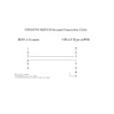
8 Pin Minature DIN to 9 Pin female D-Type
When connecting the Fortronic F85 terminal with 8 Pin DIN
sockets to the ERA570 or ERA610 the following cable should
be used.
sockets to the ERA570 or ERA610 the following cable should
be used.
Note : Pins 1, 6 & 8 are joined together on ECR connector.
The pin connections (looking at the back of the F85) are :
Sharp Part Number for 8 Pin Minature DIN to 9 Pin female
D-Type
D-Type
F858PINCABLE Price Code AU
6
3
SD
DSR
8
CTS
2
RD
ECR side (9 pin Female)
F85 8 Pin Din
1
5
GND
1 - Transmit Data
7
RTS
3 - In 1
8 - Ground
2 - Recieve Data
5 - Out 2
DCD
1
2
3
4
5
6
7
8
ERA570 EFT Interface
1
RJ45 to 9 Pin female D-Type
When connecting the Fortronic F85 terminal with RJ45 sock-
ets to the ERA570 or ERA610 the following cable should be
used.
ets to the ERA570 or ERA610 the following cable should be
used.
Note : Pins 1, 6 & 8 are joined together on ECR connector.
The pin connections (looking at the back of the F85) are :
Sharp Part Number for RJ45 to 9 Pin female D-Type
F85RJ45CABLE Price Code AU
Installation
To install the F85 credit authorisation terminal and ERA570 or
ERA610 the following steps should be taken :-
ERA610 the following steps should be taken :-
1. Fit the ERA57EFT EPROMs :
•
U033n is fitted in the main EPROM socket IC5
•
R033n is fitted in the option EPROM socket IC7
OR
1. Fit the ERA61EFT EPROMs :
•
U034n is fitted in the main EPROM socket IC5
•
R034n is fitted in the option EPROM socket IC7
(Note that ‘n’ denotes the version number)
2. Perform a MASTER RESET after fitting the new EPROMS.
3.
Fit the ERA5RS as specified in the ERA57/610 option
manual
manual
4.
Connect the cable between the selected port (as set in
946-D) on the ERA5RS and the F85 terminal ( Port 1).
946-D) on the ERA5RS and the F85 terminal ( Port 1).
5.
To confirm that the EPROMs are fitted correctly and are
functioning, carry out a 959 x TL in PGM2 mode. The
ECR should report U033n & R033n on an ERA570, or
U034n & R034n on an ERA610.
functioning, carry out a 959 x TL in PGM2 mode. The
ECR should report U033n & R033n on an ERA570, or
U034n & R034n on an ERA610.
HARDWARE
ECR - F85 Terminal
The baud rate on both devices must be set up to match each
other. The ECR is programmed to use a fixed rate of 2400
baud. Consult the F85 documentation or your Fortronic repre-
sentative regarding setting this up on the F85 terminal.
other. The ECR is programmed to use a fixed rate of 2400
baud. Consult the F85 documentation or your Fortronic repre-
sentative regarding setting this up on the F85 terminal.
The F85 terminal must be set for :
•
ECR Enabled
•
F85 standard interface
•
2400 baud
6
3
SD
DSR
8
CTS
2
RD
ECR side (9 pin Female)
F85 RJ45
1
5
GND
7 - Transmit Data
7
RTS
3 - In 1
4 - Ground
1 - Recieve Data
2 - Out 2
DCD
Pin1
Pin8
ERA570 EFT Interface
2
Chapter 2. Service (SRV) Mode
[JOB#946] MRS ERA570 = 0000 / ERA610 = 1000
The assignment of RS232 channel by each device.
#946-A:
1. Channel Number for Scanner
1. Channel No. for Scanner (ER-A6HS1)
946-A
Channel No.
0 to 7
#946B,C:
Not Used (Fixed at "00")
#946-D:
2. Channel Number for Fortronic F-85 Terminal
1. Channel No. for F-85 Terminal
946-D
Channel No.
0 to 7
[JOB#902] MRS 0000
#902-D
EFT Terminal
1. EFT Terminal
902-D
No
0
Yes
4
[JOB#916] MRS 1400
The default value of 916-B has been changed to 4. This al-
lows refunds to be made on CREDIT payment keys.
lows refunds to be made on CREDIT payment keys.
CHAPTER 3. PGM (PGM) MODE
The following Jobs have been ammended :
[JOB#2320]
MEDIA KEY PROGRAMMING
XXX : Function No.
Function
No.
Function
A
59
CREDIT 1
1/0
60
CREDIT 2
1/0
61
CREDIT 3
1/0
62
CREDIT 4
1/0
63
CREDIT 5
1/0
64
CREDIT 6
1/0
65
CREDIT 7
1/0
66
CREDIT 8
1/0
Where EFT enable A = 1
For the above CREDIT payment functions item A is used to
enable use of the F85 terminal.
enable use of the F85 terminal.
A:
1. EFT Function
A
Disable
0
Compulsory
1
[JOB#2641]
MESSAGE TEXT PROGRAMMING
The following additions have been made to the message text
file
The following additions have been made to the message text
file
X = Message No. = 1-83
Message
No.
Description
MRS
76
Comms Error
EFT COMS ERR
77
Other Error
GEN EFT ERR
78
Hotcard Found
HOT CARD
79
Card Expired
CARD EXPIRED
80
Card is not yet valid.
PRE-VALID
81
Cancelled by operator
OP CANCELLED
82
Signature rejected
BAD SIGNATUR
83
Authorisation was declined
DECLINED
TL
ST
XXX
2320
X
X
ABCDEFGHIJKL
2641
X
XX
X
{Text}
ST
Max 12 Char
TL
946
A B C D
X
TL
ERA570 EFT Interface
3

