Sharp DX-AT50H (serv.man9) Service Manual / Specification ▷ View online
– 19 –
DX-AT50H
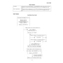
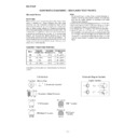
7. To select No. 3 "ERROR RATE," press button [3] on the
remote control unit.
Fig. g will appear on the screen and Fig. d will appear on the
LCD.
Fig. g will appear on the screen and Fig. d will appear on the
LCD.
E56***D FE *.*** BE *.*** AVD *.*
TEST4-MEASUREMENT MODE
DISC:DVD / DUAL LAYER / OPPOSITE
END:******H / ******H
STATUS: * * * * * * * *
DISC:DVD / DUAL LAYER / OPPOSITE
END:******H / ******H
STATUS: * * * * * * * *
PLAY MODE-ERROR RATE
1. L-0/030000 HEX
2. L-0/220000 HEX
3. L-1/FC0000 HEX
4. L-1/E00000 HEX
1. L-0/030000 HEX
2. L-0/220000 HEX
3. L-1/FC0000 HEX
4. L-1/E00000 HEX
EXIT:
POWER
RETURN:
RETURN
(I) When loading DVD
E56***D FE *.*** BE *.*** AVD *.*
TEST4-MEASUREMENT MODE
DISC: AUDIO CD
TIME: **:**
STATUS: * * * * * * * *
DISC: AUDIO CD
TIME: **:**
STATUS: * * * * * * * *
PLAY MODE-ERROR RATE
1. 00:02
2. 60:00
1. 00:02
2. 60:00
EXIT:
RETURN:
RETURN
POWER
(II) When loading CD/VCD
In "PLAY MODE-ERROR RATE" of fig. g, each item means
the following:
1. Inner circumference of loaded disc
the following:
1. Inner circumference of loaded disc
(on DVD: inner circumference of layer 0)
2. Outer circumference of loaded disc
(on DVD: outer circumference of layer 0)
3. Outer circumference of layer 1 on loaded disc
(on DVD only: when in parallel, inner circumference)
4. Inner circumference of layer 1 on loaded disc
(on DVD only: when in parallel, outer circumference)
In some cases, items 2,3 and 4 may not be shown on the
screen depending on the content of the loaded disc.
In some cases, items 2,3 and 4 may not be shown on the
screen depending on the content of the loaded disc.
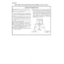
8. Select the address where the error rate is to be measured
using number buttons on the remote control unit.
Fig. h will appear on the screen. In table (*2), the screen will
show for each 80ECC block, the number of errors corrected
on the 1st PO/PI/2nd PO and the number of uncorrected
errors.
Fig. h will appear on the screen. In table (*2), the screen will
show for each 80ECC block, the number of errors corrected
on the 1st PO/PI/2nd PO and the number of uncorrected
errors.
DISC:DVD / DUAL LAYER / OPPOSITE
STATUS: * * * * * * * *
ERROR RATE SELECT NO.[4]
1. L-0/030000 HEX
2. L-0/220000 HEX
3. L-1/FC0000 HEX
4. L-1/E00000 HEX
NOW MEASURE:******H - ******H
STATUS: * * * * * * * *
ERROR RATE SELECT NO.[4]
1. L-0/030000 HEX
2. L-0/220000 HEX
3. L-1/FC0000 HEX
4. L-1/E00000 HEX
NOW MEASURE:******H - ******H
EXIT:
POWER
RETURN:
RETURN
correct
uncorrect
1 st
PO
2 nd
PO
PI
(*2)
(I) when loading DVD
DISC: AUDIO CD
STATUS: * * * * * * * *
ERROR RATE SELECT NO.[4]
1. 00:02
2. 60:00
STATUS: * * * * * * * *
ERROR RATE SELECT NO.[4]
1. 00:02
2. 60:00
NOW MEASURE: ** : ** ; ** - ** : ** : **
EXIT:
POWER
RETURN:
RETURN
correct
uncorrect
1 st
PO
2 nd
PO
PI
(*2)
(II) when loading CD/VCD
9. To finish measuring the error rate, remove the disc and turn
the power off.
Figure g Error Rate Mode Screen
Figure h Measuring Error Rate Mode Screen
Figure i LCD in Measuring Error Rate Mode (example)
Display

