Sharp SD-SH111 (serv.man21) Service Manual ▷ View online
SD-SH111
– 106 –
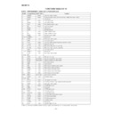
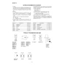
Figure 106 BLOCK DIAGRAM OF IC
IC3504 RH-iX1687GEZZ: DVD Microcomputer (IX1687GE)
Port D
PF7/ø
PF6/AS
PF5/RD
PF4/HWR
PF3/LWR
PF2/LCAS/WAIT/BREQO
PF1/BACK
PFD/BREQ
PF6/AS
PF5/RD
PF4/HWR
PF3/LWR
PF2/LCAS/WAIT/BREQO
PF1/BACK
PFD/BREQ
PG4/CS0
PG3/CS1
PG2/CS2
PG1/CS3
PG0/CAS
PG3/CS1
PG2/CS2
PG1/CS3
PG0/CAS
P67/CS7/IRO3
P66/CS8/IRO2
P66/IRQ3
P64/IRQ0
P63/TEND1
P62/DREQ1
P61/TEND0/CS5
P60/DREQ0/CS4
P66/CS8/IRO2
P66/IRQ3
P64/IRQ0
P63/TEND1
P62/DREQ1
P61/TEND0/CS5
P60/DREQ0/CS4
P10/PO8/TIOCA0/DACK0
P11/PO9/TIOCB0/DACK1
P12/PO10/TIOCC0/TCLKA
P13/PO11/TIOCD0/TCLKB
P14/PO13/TIOCA1
P15/PO13/TIOCB1/TCLKC
P16/PO14/TIOCA2
P17/PO15/TIOCB2/TCLKD
P20/PO0/TIOCA3
P21/PO1/TIOCB3
P22/PO2/TIOCC3/TMRI0
P23/PO3/TIOCD4/TMCI0
P24/PO4/TIOCA4/TMRI1
P24/PO5/TIOCB4/TMCI1
P26/PO6/TIOCA5/TMO0
P27/PO7/TIOCB5/TMO1
Vref
AVcc
AVss
P47/AN7/DA1
P45/AN6/DA0
P45/AN5
P44/AN4
P43/AN3
P42/AN2
P41/AN1
P40/AN0
PA7/A23/IRO7
PA6/A22/IRO6
PA5/A21/IRO5
PA4/A20/IRO4
PA3/A19
PA2/A18
PA1/A17
PA0/A16
PA6/A22/IRO6
PA5/A21/IRO5
PA4/A20/IRO4
PA3/A19
PA2/A18
PA1/A17
PA0/A16
PB7/A15
PB6/A14
PB5/A13
PB4/A12
PB3/A11
PA2/A10
PB1/A9
PB0/A8
PB6/A14
PB5/A13
PB4/A12
PB3/A11
PA2/A10
PB1/A9
PB0/A8
PC7/A7
PC6/A6
PC5/A5
PC4/A4
PC3/A3
PC2/A2
PC1/A1
PC0/A0
PC6/A6
PC5/A5
PC4/A4
PC3/A3
PC2/A2
PC1/A1
PC0/A0
P35/SCX1
P34/SCX0
P33/RxD1
P32/RxD0
P31/TxD1
P30/TxD0
P34/SCX0
P33/RxD1
P32/RxD0
P31/TxD1
P30/TxD0
P50/TxD2/IRD4
P51/RxD2/IRD5
P52/SCK2/IRQ6
P53/ADTRG/IRQ7
/WAIT/BREQO
P51/RxD2/IRD5
P52/SCK2/IRQ6
P53/ADTRG/IRQ7
/WAIT/BREQO
PO7/O15
PO6/O14
PO5/O13
PO4/O12
PO3/O11
PO2/O10
PO1/O9
PO0/O8
PE7/D7
PE6/D6
PE5/D5
PE4/D4
PE3/D3
PE2/D2
PE1/D1
PE0/D0
VSS
VSS
VSS
VSS
VSS
VSS
VSS
VSS
VCC
VCC
VCC
VCC
VCC
MD2
MD1
MD0
EXTAL
XTAL
STBY
RES
WOTOVF(FWE)*
MD1
MD0
EXTAL
XTAL
STBY
RES
WOTOVF(FWE)*
1
NM3
Port E
H8S/2000 CPU
DTC
DMAC
RAM*
2
Interruption controller
Clock
oscillator
Bass controller
Port B
Port A
Inside data bus
Inside address bus
Port C
Port 3
Port 5
WDT
PPG
SCI
D/A converter
A/D converter
RAM
TPU
8 bit timer
Port F
Port G
Port 6
Port 1
Port 2
Port 4
NOTE: *
1
A FWE terminal is applied only to the F-ZTA edition. A WDTOVF terminal function can't be used by the F-ZTA edition.
*
2
A ROM is applied to the master ROM edition, the ZTAT edition, the F-ZTA edition.
– 107 –
SD-SH111
1
VDDL
Input
L channel digital output section power terminal
2
OUTL (+)
Output
L channel forward output terminal
3
OUTL (–)
Output
L channel reverse output terminal
4
GNDD
—
Digital output section ground terminal
5
OUTR (–)
Output
R channel reverse output terminal
6
OUTR (+)
Output
R channel forward output terminal
7
VDDR
Input
R channel digital output section power terminal
8
VDDX
Input
Oscillation section power terminal
9
XI
Input
10
XO
Output
11
GNDX
—
Oscillation section ground terminal
12*
MCK
Output
System clock output terminal
13*
TEST
—
Test terminal. As usual, it is used at "L".
14
NFR1 (+)
Input
R channel forward signal feedback input terminal
15
NFR2 (–)
Input
R channel reverse signal feedback input terminal
16
GNDA
—
Analog ground terminal for AD converter
17
Rch IN
Input
R channel analog input terminal
18
Rch Vref
Input
Reference voltage terminal for R channel
19
Lch Vref
Input
Reference voltage terminal for L channel
20
Lch IN
Input
L channel analog input terminal
21
RESET
Input
Reset terminal. It is reset with "L".
22
NFL2 (–)
Input
L channel reverse signal feedback input terminal
23
NFL1 (+)
Input
L channel forward signal feedback input terminal
24
VDDA
Input
Analog current terminal for AD converter
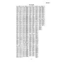
Pin No.
Port Name
Input/Output
Function
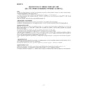
In this unit, the terminal with asterisk mark (*) is (open) terminal which is not connected to the outside.
ICA100 RH-iX0498AWZZ: 7th Order Modulation Conversion LSI (IX0498AW)
1
2
3
4
5
6
7
8
9
10
11
12
24
23
22
21
20
19
18
17
16
15
14
13
VDDL
VDDA
NFL1(+)
NFL2(–)
RESET
Lch IN
Lch Vref
Rch Vref
Rch IN
GNDA
NFR2(–)
NFR1(+)
TEST
OUTL(+)
OUTL(–)
GNDD
OUTR(–)
OUTR(+)
VDDR
VDDX
XI
XO
GNDX
MCK
1
2
3
4
5
6
7
8
9
10
11
12
24
23
22
21
20
19
18
17
16
15
14
13
VDA
NFL1(+)
NFL2(–)
RESET
Lch IN
Lch Vref
Rch Vre
f
Rch IN
GNDA
NFR2(–)
NFR1(+)
TEST
VDDL
OUTL(+)
OUTL(–)
GNDD
OUTR(–)
OUTR(+)
VDDR
VDDX
XI
XO
GNDX
MCK
Comparator
Comparator
Amplitude Doubling
Converter
Amplitude Doubling
Converter
Oscillator
Lch 7th order
Modulation Circuit
Rch 7th order
Modulation Circuit
Figure 107 BLOCK DIAGRAM OF IC

