Sharp SD-PX15H (serv.man13) Service Manual ▷ View online
SD-PX15H
2 – 9
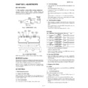
7. CD-ROM Write Mode
7.1. Outline
DVD-ROM can be upgraded from CD-ROM. The write mode is
entered from the normal mode.
entered from the normal mode.
1. When any CD-ROM for version upgrade DVD is detected, the sta-
tus informs that the version upgrade ROM is being read.
When DVD microcomputer is changed to System microcomputer
and byte 24 status data detects 0Fh:
and byte 24 status data detects 0Fh:
• The TEST Mode is entered by the status reception. (Required to
be internally recognized.)
• The Power button /Function switching is prohibited.
(Power supply is necessary until write is completed.)
• It is prohibited to accept any button input until write is com-
pleted.
• Change the display as follows:
Upper 5 x 7 dots: ROM_
Lower 5 x 7 dots: READING_
2. To expand into RAM, DVD performs read-operation.
3. When reading ends, transmission stops for writing.
(Ignore stoppage of transmission during write.)
When transmission stops, the transmission port receives write
states, which are displayed according to port states.
states, which are displayed according to port states.
Upper display section: ROM_
Lower display section: W: ***_
4. To open the DVD/CD door when end of rewrite is detected.
(The DVD status is not relevant since there is no communication.)
5. To close the DVD/CD door, cancel the TEST Mode and reset when
the Power button is pressed.
[4] Description on the Circuits of the 1-Bit
Unit (See the wiring diagrams on pages 6-
24 - 6-25.)
Unit (See the wiring diagrams on pages 6-
24 - 6-25.)
1. Input Part
Signals input from BIA102 are input to the AD conversion IC (ICA101,
ICA201 and ICA301) coupled by “CA101, CA102, CA201, CA202,
CA301 and CA302.
ICA201 and ICA301) coupled by “CA101, CA102, CA201, CA202,
CA301 and CA302.
2.
Modulation 1-Bit Converter
Signals input to the AD conversion ICs (ICA101, ICA201 and ICA301)
are converted into 1-bit signals for differential output. For detailed
description of the conversion into 1-bit signals, refer to the Technical
Manual for SM-SX100 already published.
are converted into 1-bit signals for differential output. For detailed
description of the conversion into 1-bit signals, refer to the Technical
Manual for SM-SX100 already published.
3. Low Pass Filter Circuit
The 1-bit signals switched at the output ICs (ICA102, ICA202 and
ICA302) are converted into analog signals by passing through the low
pass filter consisting of LA104 to LA104, LA201 to LA204 and LA301
to LA304.
ICA302) are converted into analog signals by passing through the low
pass filter consisting of LA104 to LA104, LA201 to LA204 and LA301
to LA304.
The property of low pass filter is flat up to 20 kHz and attenuated at
approx. 40 kHz by approx. 3 dB.
approx. 40 kHz by approx. 3 dB.
4. Dynamic Feedback Circuit
The 1-bit signals switched at the output ICs (ICA102, ICA202 and
ICA302) are amplified between plus power and GND.
ICA302) are amplified between plus power and GND.
By resistive division, the 1-bit signals pass through 75 k
Ω of NF resis-
tance (RA111 to RA114, RA211 to RA214, RA311 to RA314) and are
fed back to the AD conversion IC (ICA101, ICA201 and ICA301). P-P
voltage at this time is approx. 5 V.
fed back to the AD conversion IC (ICA101, ICA201 and ICA301). P-P
voltage at this time is approx. 5 V.
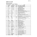
DVD DATA
DVD CLK
State
Unit display
1
L
H
—
No display
2
H
L
During write
W : S T R
3
H
H
Write ended
W : E N D
4
L
L
Write error
W : E R R
SD-PX15H
2 – 10
[5] Confirming and Canceling the Detection
Line of the Protect Circuit
Line of the Protect Circuit
1. When power is on, the microcomputers (IC002) installed in this
model continuously monitor the following abnormal operations. If
any abnormality occurs, all power except for the circuit driving
these microcomputers are cut off immediately.
any abnormality occurs, all power except for the circuit driving
these microcomputers are cut off immediately.
1) An abnormal drop in the regulator output voltage.
2) Excessive output offset of the 1-bit amplifier.
(Power cut off immediately after direct current potential exceeds
approx. 2 V.)
approx. 2 V.)
3) Excessive main power supply current of the 1-bit amplifier.
4) Abnormalities detected in the cooling fan motor and its drive cir-
cuit. (Stop, etc.)
Power cut off after “FAN LOCK” displayed.
2. How the microcomputers judge abnormalities and confirming and
canceling the detection line.
Conditions:
1) Abnormalities detected according to the voltages on pin 91 of
IC002 (PROTECT).
2) An abnormality detected when pulse signals input to pin 26
(FAN LOCK) of IC002 are lost for 5 sec.
3. Confirming and canceling the detection line.
CAUTION: When the above failures 1) and 2) are detected and the
detection lines (PROTECT and FAN LOCK) are discon-
nected, protection of the microcomputer does not work.
nected, protection of the microcomputer does not work.
If the cause is short circuits of regulators and the detection
lines are disconnected, the parts and PWBs may burn out.
Therefore do not disconnect these lines unless it is clear
that the cause is the failures 1) and 2).
lines are disconnected, the parts and PWBs may burn out.
Therefore do not disconnect these lines unless it is clear
that the cause is the failures 1) and 2).
(After a failure, a current is supplied for approx. 0.5 sec-
onds which can be observed with an oscilloscope. It is hard
to observe a current with a tester since rising and falling
edges are steep.)
onds which can be observed with an oscilloscope. It is hard
to observe a current with a tester since rising and falling
edges are steep.)
1) If an abnormal drop in the regulator output voltage is detected,
connect the measuring instrument (the oscillograph, etc.) to the
regulator stabilized output and then turn on the power of the set.
regulator stabilized output and then turn on the power of the set.
When the output voltage is significantly lower than the stabilized
output voltage shown in the circuit diagram, the regulator itself
and its destination circuit are doubtful.
output voltage shown in the circuit diagram, the regulator itself
and its destination circuit are doubtful.
2) Excessive output offset of the 1-bit amplifier is detected, remove
BIA103 and then turn on the power of the set for normal opera-
tion.
tion.
• After repairing, adjust the output offset voltage of the 1-bit
amplifier.

