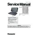
Panasonic DVD-LS70EB / DVD-LS70EE / DVD-LS70EG / DVD-LS92EB / DVD-LS92EE / DVD-LS92EG Service Manual ▷ View online
ORDER NO.CHM1103015CE
Portable DVD/CD PLAYER
Model No.
DVD-LS70EB
DVD-LS70EE
DVD-LS70EG
DVD-LS92EB
DVD-LS92EE
DVD-LS92EG
DVD-LS70EE
DVD-LS70EG
DVD-LS92EB
DVD-LS92EE
DVD-LS92EG
RAE1910Z-3C Mechanism Series
Colour
(K).......................Black Type
(K).......................Black Type
2
TABLE OF CONTENTS
PAGE
PAGE
1 IMPORTANT SERVICE INFORMATION ---------------------3
1.1. Notes ----------------------------------------------------------3
1.2. About DivX---------------------------------------------------3
1.3. Manual for Customer--------------------------------------4
1.2. About DivX---------------------------------------------------3
1.3. Manual for Customer--------------------------------------4
2 SAFETY PRECAUTIONS ----------------------------------------5
2.1. GENERAL GUIDELINES --------------------------------5
2.2. Caution for AC Mains Lead (Only for LS70EB/
2.2. Caution for AC Mains Lead (Only for LS70EB/
LS92EB)------------------------------------------------------6
3 PREVENTION OF ELECTRO STATIC DISCHARGE
(ESD) TO ELECTROSTATICALLY SENSITIVE (ES)
DEVICES -------------------------------------------------------------7
DEVICES -------------------------------------------------------------7
4 PRECAUTION OF LASER DIODE ----------------------------8
5 SPECIFICATIONS -------------------------------------------------9
6 HOW TO REPLACE THE LITHIUM BATTERY ---------- 11
7 SERVICE CAUTION BASED ON LEGAL
5 SPECIFICATIONS -------------------------------------------------9
6 HOW TO REPLACE THE LITHIUM BATTERY ---------- 11
7 SERVICE CAUTION BASED ON LEGAL
RESTRICTIONS -------------------------------------------------- 12
7.1. General description about Lead Free Solder
(PbF) -------------------------------------------------------- 12
8 HANDLING PRECAUTIONS FOR TRAVERSE
DECK ---------------------------------------------------------------- 13
8.1. Handling of optical pickup------------------------------ 13
8.2. Grounding for electrostatic breakdown
8.2. Grounding for electrostatic breakdown
prevention-------------------------------------------------- 13
9 DISASSEMBLY, REASSEMBLY AND SERVICE
POSITION ---------------------------------------------------------- 14
9.1. Disassembly ----------------------------------------------- 15
9.2. P.C.B. location -------------------------------------------- 16
9.3. Main cabinet of the unit--------------------------------- 16
9.4. Traverse assembly--------------------------------------- 17
9.5. Optical pick-up unit -------------------------------------- 18
9.6. Disc motor-------------------------------------------------- 18
9.7. Main P.C.B. ------------------------------------------------ 19
9.8. Operation P.C.B.------------------------------------------ 19
9.9. Monitor assembly ---------------------------------------- 19
9.10. Disc cover-------------------------------------------------- 20
9.11. Monitor cover---------------------------------------------- 20
9.12. Inverter P.C.B.--------------------------------------------- 21
9.13. LCD panel-------------------------------------------------- 21
9.14. Replacing the fuse in the car dc adaptor----------- 21
9.15. Service position------------------------------------------- 22
9.13. LCD panel-------------------------------------------------- 21
9.14. Replacing the fuse in the car dc adaptor----------- 21
9.15. Service position------------------------------------------- 22
10 SELF-DIAGNOSIS FUNCTION AND SERVICE
MODE --------------------------------------------------------------- 23
10.1. Optical Pickup Breakdown Diagnosis--------------- 23
10.2. DVD Self Diagnostic Function-Error Code--------- 24
10.3. Last Error Code saved during NO PLAY ----------- 24
10.4. Special Operation Menu-------------------------------- 25
10.5. Lens cleaning --------------------------------------------- 26
10.2. DVD Self Diagnostic Function-Error Code--------- 24
10.3. Last Error Code saved during NO PLAY ----------- 24
10.4. Special Operation Menu-------------------------------- 25
10.5. Lens cleaning --------------------------------------------- 26
11 SERVICE PRECAUTIONS------------------------------------- 27
11.1. Firmware version-up of the DVD player ------------ 27
12 ADJUSTMENT PROCEDURES ------------------------------ 28
12.1. Service Tools and Equipment ------------------------- 28
12.2. Important points in adjustment ----------------------- 28
12.3. Storing and Handling Test Discs --------------------- 28
12.4. Optical adjustment--------------------------------------- 28
12.3. Storing and Handling Test Discs --------------------- 28
12.4. Optical adjustment--------------------------------------- 28
13 ABBREVIATIONS ----------------------------------------------- 31
14 VOLTAGE CHART ---------------------------------------------- 33
14 VOLTAGE CHART ---------------------------------------------- 33
14.1. MAIN P.C.B.----------------------------------------------- 33
15 BLOCK DIAGRAM ---------------------------------------------- 35
15.1. OVERALL BLOCK DIAGRAM------------------------ 35
15.2. POWER SUPPLY BLOCK DIAGRAM-------------- 36
15.3. SERVO BLOCK DIAGRAM --------------------------- 37
15.4. AUDIO BLOCK DIAGRAM ---------------------------- 38
15.5. VIDEO BLOCK DIAGRAM ---------------------------- 39
15.2. POWER SUPPLY BLOCK DIAGRAM-------------- 36
15.3. SERVO BLOCK DIAGRAM --------------------------- 37
15.4. AUDIO BLOCK DIAGRAM ---------------------------- 38
15.5. VIDEO BLOCK DIAGRAM ---------------------------- 39
16 SCHEMATIC DIAGRAM & SCHEMATIC DIAGRAM
NOTES-------------------------------------------------------------- 40
16.1. SCHEMATIC DIAGRAM NOTES -------------------- 40
16.2. INTERCONNECTION SCHEMATIC
16.2. INTERCONNECTION SCHEMATIC
DIAGRAM ------------------------------------------------- 41
16.3. CHARGE BATTERY SECTION (MAIN P.C.B.
(1/9)) SCHEMATIC DIAGRAM ----------------------- 42
16.4. POWER SUPPLY SECTION (MAIN P.C.B. (2/
9)) SCHEMATIC DIAGRAM--------------------------- 43
16.5. OPTICAL PICK UP/SERVO SECTION (MAIN
P.C.B. (3/9)) SCHEMATIC DIAGRAM -------------- 44
16.6. DV5 SECTION (MAIN P.C.B. (4/9))
SCHEMATIC DIAGRAM ------------------------------- 45
16.7. DV5 SECTION (MAIN P.C.B. (5/9))
SCHEMATIC DIAGRAM ------------------------------- 46
16.8. VIDEO OUT SECTION (MAIN P.C.B. (6/9))
SCHEMATIC DIAGRAM ------------------------------- 47
16.9. AUDIO OUT SECTION (MAIN P.C.B. (7/9))
SCHEMATIC DIAGRAM ------------------------------- 48
16.10. OPERATION SECTION (MAIN P.C.B. (8/9))
SCHEMATIC DIAGRAM ------------------------------- 49
16.11. LCD IF SECTION (MAIN P.C.B. (9/9))
SCHEMATIC DIAGRAM ------------------------------- 50
16.12. OPERATION SECTION (OPERATION P.C.B.)
SCHEMATIC DIAGRAM ------------------------------- 51
16.13. I/F SECTION (INVERTER P.C.B.)
SCHEMATIC DIAGRAM ------------------------------- 52
17 CIRCUIT BOARD ASSEMBLY------------------------------- 53
17.1. MAIN P.C.B. (1/2) (COMPONENT SIDE)---------- 53
17.2. MAIN P.C.B. (2/2) (FOIL SIDE) ---------------------- 54
17.3. OPERATION P.C.B.------------------------------------- 55
17.4. INVERTER P.C.B. --------------------------------------- 56
17.2. MAIN P.C.B. (2/2) (FOIL SIDE) ---------------------- 54
17.3. OPERATION P.C.B.------------------------------------- 55
17.4. INVERTER P.C.B. --------------------------------------- 56
18 EXPLODED VIEW AND REPLACEMENT PARTS
LIST ----------------------------------------------------------------- 57
18.1. Exploded Views and Mechanical
Replacement Parts List -------------------------------- 57
18.2. Electrical Replacement Parts List ------------------- 62
19 SCHEMATIC DIAGRAM FOR PRINTING WITH A4---- 68
3
1 IMPORTANT SERVICE INFORMATION
1.1.
Notes
When you replace FLASH ROM or exchange MAIN P.C.B., you have to take “Manual for customer” to the customer with unit (also
in the case of unit exchanges.).
Please take and use “Manual for customer” from below.
in the case of unit exchanges.).
Please take and use “Manual for customer” from below.
1. Come with MAIN P.C.B. or FLASH ROM (Service part).
2. Make a photocopy section 1.3 “Manual for customer” on this Service Manual.
2. Make a photocopy section 1.3 “Manual for customer” on this Service Manual.
“Manual for customer” has important information for “DivX Video-on-Demand Service” user.
Please don’t forget take it to the customer with unit!
Please don’t forget take it to the customer with unit!
1.2.
About DivX
1.2.1.
DivX
A video compression format developed by DivXNetworks, Inc. that compresses video files without any considerable loss of video
quality.
quality.
1.2.2.
About DivX
®
VOD Content
4
1.2.3.
About DivX subtitles text display (Only for LS70EB/EG/LS92EB/EG)
1.3.
Manual for Customer

