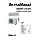
Panasonic CS-MC90KH / CU-MC140KH / CS-MC90KH / CU-MC180KH / CS-MC90KH / CU-3MC200KH Service Manual ▷ View online
– 8 –
ORDER NO. MAC9807010C3
CS-MC90KH
Product Specifications
Description
Tube material
Fin material
Fin Type
Row / Stage
Tube material
Fin material
Fin Type
Row / Stage
FPI
Size (W
Size (W
×
H
×
L)
µ
F, VAC
µ
F, VAC
Length
Flow Rate
Inner Diameter
Material
Style
Flow Rate
Inner Diameter
Material
Style
Heat
Exchanger
Exchanger
Refrigerant Control Device
Refrigeration Oil
Refrigerant (R-22)
Thermostat
Protection Device
Thermostat
Protection Device
Capillary Tube
Air Filter
Capacity Control
Compressor Capacitor
Compressor Capacitor
Fan Motor Capacitor
Unit
mm
(c.c)
g (oz)
mm
s
/min
mm
(Plate fin configuration, forced draft)
Capillary Tube
CS-MC90KH
Evaporator
Copper
Aluminium
Slot Fin
2
×
12
17
600
×
252
×
25.4
–
–
–
Electronic Control
–
–
–
–
–
–
–
P.P.
Honeycomb
–
0.6
µ
F, 400 VAC
CU-MC180KH
Condenser
Copper
Aluminium
Corrugated Fin
2
×
24
16
560
×
609.6
×
44
Capillary Tube
SUNISO 4GDID or
ATMOS M60 (270)
ATMOS M60 (270)
650
×
2 (22.9
×
2)
–
Overload Protector
1,170
10.0
1.6
–
25
µ
F, 370 VAC
3.0
µ
F, 450 VAC
• Specifications are subject to change without notice for further improvement.
Untitled-16
6/26/00, 3:36 PM
8
– 9 –
ORDER NO. MAC9807010C3
CS-MC90KH
Product Specifications
Unit
kW
Btu/h
s
/h
Pint/h
Phase
V
Cycle
OUTLET
INTAKE
m
3
/min (cfm)
m
3
/min (cfm)
m
3
/min (cfm)
m
3
/min (cfm)
dB (A)
kW
A
W/W
A
inch
inch
inch
inch
mm
m
inch (mm)
inch (mm)
inch (mm)
lb (kg)
W
W
W
rpm
rpm
rpm
CS-MC90KH
Single Operation
(A, B1, B2)
–
–
SIDE VIEW
7.2 (250)
7.4 (260)
7.5 (260)
–
High 36-35, Low 31-29
0.030-0.025
0.14-0.13
–
(A unit) 16-15
G ; Half Union 3/8"
L ; Half Union 1/4"
G (gas side) ; 3/8"
L (liquid side) ; 1/4"
12
0.7
11-7/16 (290)
31-15/32 (799)
6-29/32 (175)
18 (8.0)
–
–
–
Cross-flow Fan
AS + Glass Fiber 30%
Induction (4-poles)
22
5
990
1,100
1,180
Indoor Air (Lo)
Indoor Air (Me)
Indoor Air (Hi)
Outdoor Air
Input
Running Current
COP
Starting Current
Inner diameter
Length
Height
Width
Depth
Type
Motor
Type
Rated Output
Type
Material
Motor
Type
Input
Rated Output
Fan
Low
Speed Medium
High
Single Operation
Double Operation
Triple Operation
(A)
(B1 or B2)
(B1 + B2)
(A +B1 or B2) (A + B1 + B2)
2.40-2.34
2.82-2.78
3.60-3.52
5.22-5.12
6.00-5.86
8,200-8,000 9,600-9,500 12,300-12,000 17,800-17,500 20,500-20,000
1.5
1.7-1.6
2.1-2.0
2.9-2.8
3.3-3.2
3.2
3.6-3.4
4.4-4.2
6.1-5.9
7.0-6.8
Single
240 - 220
50
0.79-0.75 1.09-1.05 1.15-1.10
1.79-1.70
1.83-1.77
3.36-3.47 4.76-4.77 4.92-5.04
7.62-7.74
7.78-8.07
2.93-3.04 2.52-2.60 2.98-3.06
2.82-2.93
3.13-3.18
Cooling Capacity Per Unit
Moisture Removal
Power Source
Airflow Method
Air Volume
Noise Level
Electrical
Data
Data
Piping Connection Port
(Flare piping)
(Flare piping)
Pipe Size
(Flare piping)
(Flare piping)
Drain
Hose
Dimensions
Net Weight
Compressor
Air
Circulation
Circulation
CU-3MC200KH
TOP VIEW
–
–
–
–
56 - 54
(B unit) 22-21
G ; 3-way valve 3/8"
L ; 2-way valve 1/4"
G (gas side) ; 3/8"
L (liquid side) ; 1/4"
–
–
25-21/32 (651)
35-3/16 (893)
13-19/32 (345)
141 (64)
Rotary (1 cylinder)
rolling piston type
Induction (2-poles)
650 + 900
Propeller Fan
AES + Glass Fiber 16%
Induction (6-poles)
108
37
–
–
730
Untitled-16
6/26/00, 3:36 PM
9
– 10 –
ORDER NO. MAC9807010C3
CS-MC90KH
Product Specifications
Heat
Exchanger
Exchanger
Refrigerant Control Device
Refrigeration Oil
Refrigerant (R-22)
Thermostat
Protection Device
Thermostat
Protection Device
Capillary Tube
Air Filter
Capacity Control
Compressor Capacitor
Compressor Capacitor
Fan Motor Capacitor
Unit
mm
(c.c)
g (oz)
mm
s
/min
mm
µ
F, VAC
µ
F, VAC
Length
Flow Rate
Inner Diameter
Material
Style
Flow Rate
Inner Diameter
Material
Style
• Specifications are subject to change without notice for further improvement.
(Plate fin configuration, forced draft)
Capillary Tube
Description
Tube material
Fin material
Fin Type
Row / Stage
Tube material
Fin material
Fin Type
Row / Stage
FPI
Size (W
×
H
×
L)
CU-3MC200KH
Condenser
Copper
Aluminium
Corrugated Fin
2
×
24
16
756.0
×
609.6
×
44
719.5
Capillary Tube
SUNISO 4GDID or
ATMOS M60
650 (23.0), 950 (33.5)
–
2 Stage-Overload Protector
935, 920, 1,170
20.0, 15.5, 10.0
20.0, 15.5, 10.0
2.0, 1.8, 1.6
–
25
µ
F, 440 VAC
3.0
µ
F, 450 VAC
CS-MC90KH
Evaporator
Copper
Aluminium
Slot Fin
2
×
12
17
600
×
252
×
25.4
–
–
–
Electronic Control
–
–
–
–
–
–
–
P.P.
Honeycomb
–
0.6
µ
F, 400 VAC
Untitled-16
6/26/00, 3:36 PM
10
– 11 –
ORDER NO. MAC9807010C3
CS-MC90KH
Dimensions
CS-MC90KH
Relative position between the indoor unit and the installation plate <Front View>
(45)
(410)
<Back View>
Installation plate hooks
Drain ports
Gas
side
side
Liquid
side
Remote control transmitter
57
142
16
(44)
710
(45)
276
7
(64)
(115)
100
100
Slot (2 places)
Slot (2 places)
Centre notch
Indoor unit external
dimensions line
dimensions line
Installation plate
Left piping hole
Arrow
Arrow
Centre
Right piping hole
Installation plate positioning gauge
350
7
457
13.5
799
48.5
60
290
<Front View>
175
61
34.5
52
direction
Air intake
Air outlet
direction
direction
Left piping hole
Right piping hole
290
115
55
60
Untitled-17
6/26/00, 3:38 PM
11
Click on the first or last page to see other CS-MC90KH / CU-MC140KH / CS-MC90KH / CU-MC180KH / CS-MC90KH / CU-3MC200KH service manuals if exist.

