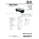
Sony ZS-X1 Service Manual ▷ View online
5
ZS-X1
SECTION 2
GENERAL
This section is extracted from
instruction manual.
instruction manual.
To turn on/off the power
European model: Press OPERATE.
Other models: Press POWER.
To adjust the volume
Press VOL +, –.
To listen through headphones
Connect the headphones to the i (headphones) jack.
Adjusting the sound emphasis
To reinforce the bass sound
Press MEGA BASS.
“MEGA BASS” appears in the display.
To return to normal sound, press the button again.
Location of controls
Total track number
Programmed track
Playing order
C
D
Total playing time
Display/Visor
MEGA BASS
VOL –, +*
DISPLAY/ENT
MEMORY
MEMORY
MODE
i
x
u
*
POWER
(US, CND, SP, KR, AUS models)
OPERATE
(AEP, UK, IT, EE models)
DC IN 9V
OPR/BATT
Loading a CD
With the labeled side up
ESP
BAND
AUTO PRESET
AUTO PRESET
ESP indicator
Indicador ESP
Indicador ESP
Display
Visor
Visor
*The button has a tactile dot.
Z
PUSH
OPEN/CLOSE
Note
When inserting a CD, place the player horizontally.
If the player is not level, you cannot open or close the CD compartment lid.
If the player is not level, you cannot open or close the CD compartment lid.
• Abbreviation
AUS : Australian model
CND : Canadian model
EE
CND : Canadian model
EE
: East European model
IT
: Italian model
KR
: Korean model
SP
: Singapore model
Ver 1.1
ZS-X1
6
• This set can be disassembled in the order shown below.
3-1.
DISASSEMBLY FLOW
SECTION 3
DISASSEMBLY
3-2. CABINET LOWER ASSY,
TELESCOPIC ANTENNA (ANT1)
(Page 7)
(Page 7)
3-3. MAIN CHASSIS SECTION
(Page 8)
3-4. AUDIO BOARD,
BATTERY BOARD
(Page 8)
(Page 8)
3-5. TUNER BOARD,
CONTROL BOARD
(Page 9)
(Page 9)
3-6. CD MECHANISM
DECK SECTION
(Page 10)
(Page 10)
3-7. OPTICAL PICK-UP
(KSS-213R)
(Page 10)
(Page 10)
3-8. CABINET FRONT SECTION
(Page 11)
3-9. SPEAKER (10cm) (L) (SP101),
SPEAKER (10cm) (R) (SP201)
(Page 11)
(Page 11)
3-10. LID CD ASSY
(Page 12)
SET
ZS-X1
7
Note:
Follow the disassembly procedure in the numerical order given.
3-2.
CABINET LOWER ASSY, TELESCOPIC ANTENNA (ANT1)
1
Open the CD lid.
2
screw
(BVTP3
(BVTP3
×
14)
3
battery case lid
4
two screws
(BVTP3
(BVTP3
×
14)
4
five screws
(BVTP3
(BVTP3
×
14)
4
five screws
(BVTP3
(BVTP3
×
14)
6
cabinet lower
assy
assy
7
telescopic antenna
(ANT1)
(ANT1)
A
!
telescopic antenna
(ANT1)
(ANT1)
main chassis
Note: Install the telescopic antenna with engaging
the
!
portion to the main chassis, then
check that the antenna is engaged and
does not move even trying to rotate it
in the direction of arrow
does not move even trying to rotate it
in the direction of arrow
A
.
5
screw
(B3
(B3
×
8)
ZS-X1
8
5
audio board
4
three screws
(BVTP3
(BVTP3
×
10)
2
two terminals
1
wire (flat type) (18 core)
(CN301)
(CN301)
3
connector
(CN901)
(CN901)
9
battery board
8
claw
6
Remove the connector lead wire
from the incision.
from the incision.
7
terminal
3-3.
MAIN CHASSIS SECTION
6
wire (flat type) (14 core)
(CN804)
(CN804)
5
wire (flat type) (27 core)
(CN803)
(CN803)
3
four screws
(BVTP3
(BVTP3
×
10)
7
main chassis section
4
1
connector (CN302)
2
connector (CN303)
3-4.
AUDIO BOARD, BATTERY BOARD
Click on the first or last page to see other ZS-X1 service manuals if exist.

