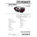
Sony CFD-RG880CP (serv.man2) Service Manual ▷ View online
SERVICE MANUAL
CFD-RG880CP
CFD-RG880CP
1
CFD-RG880CP
9-889-387-81
E Model
East European Model
Russian Model
Ver. 1.1 2013.11
The CD KEY, FUNCTION KEY, HEADPHONE, LCD, LED1, LED2, LED3, LED4,
MAIN, POWER, POWER KEY, SOUND KEY, TUNER, USB, VOLTAGE SELEC-
TOR and VOLUME KEY boards have been changed in the midway of production.
New/former discrimination, printed wiring board, schematic diagram and electri-
cal parts list of the CD KEY, FUNCTION KEY, HEADPHONE, LCD, LED1, LED2,
LED3, LED4, MAIN, POWER, POWER KEY, SOUND KEY, TUNER, USB, VOLT-
AGE SELECTOR and VOLUME KEY boards of New type are described in this
service manual SUPPLEMENT-1.
Refer to original service manual for information of Former type.
File this supplement with the service manual.
Subject: Change of the CD KEY, FUNCTION KEY, HEADPHONE,
LED1, LED2, LED3, LED4, MAIN, POWER, POWER KEY,
SOUND KEY and VOLUME KEY boards (Suffi x-21)
SOUND KEY and VOLUME KEY boards (Suffi x-21)
Change of the LCD, TUNER and USB boards (New Part
No.)
No.)
Change of the VOLTAGE SELECTOR board (Suffi x-12)
1.
NEW/FORMER DISCRIMINATION
.................
1
2. DIAGRAMS
2-1. Block Diagram - MAIN, TUNER Section - ................... 2
2-2. Block
2-2. Block
Diagram
- PANEL, POWER SUPPLY Section - ........................... 3
2-3. Schematic Diagram - MAIN Section (1/3) - ................... 5
2-4. Schematic Diagram - MAIN Section (2/3) - ................... 6
2-5. Schematic Diagram - MAIN Section (3/3) - ................... 7
2-6. Printed Wiring Board - MAIN Board - ........................... 8
2-7. Printed Wiring Boards - JACK Section - ........................ 9
2-4. Schematic Diagram - MAIN Section (2/3) - ................... 6
2-5. Schematic Diagram - MAIN Section (3/3) - ................... 7
2-6. Printed Wiring Board - MAIN Board - ........................... 8
2-7. Printed Wiring Boards - JACK Section - ........................ 9
TABLE OF CONTENTS
SUPPLEMENT-1
1. NEW/FORMER DISCRIMINATION
Confi rm by the serial number of the this unit.
– Bottom View –
(The state that removed the BATTERY LID)
Serial number
Serial Number
Destination
Former type
New type
120V AC area in E model (E92)
1054964 or smaller
1054965 or larger
East European and Russian models (CET)
1039584 or smaller
1039585 or larger
230V AC area in E model (E41)
1013836 or smaller
1013837 or larger
Mexican model (MX)
1234552 or smaller
1234553 or larger
Brazilian model (BR)
1012098 or smaller
1012099 or larger
2-8. Printed Wiring Board - TUNER Board - ........................ 10
2-9. Schematic Diagram - TUNER Board - ........................... 11
2-10. Printed Wiring Board - LCD Board - .............................. 12
2-11. Schematic Diagram - LCD Board - ................................ 13
2-12. Printed Wiring Boards - KEY Section - .......................... 14
2-13. Schematic Diagram - KEY Section - .............................. 15
2-14. Printed Wiring Boards - POWER Section - .................... 16
2-15. Schematic Diagram - POWER Section - ........................ 17
3
ELECTRICAL PARTS LIST
.............................. 21
CFD-RG880CP
CFD-RG880CP
2
2
2-1. BLOCK DIAGRAM - MAIN, TUNER Section -
A
CD L-CH
R-CH
MUTE
Q101
AMP
Q301
AGC
DRIVE
Q304
STBY
POWER AMP
IC303
R-CH
J391
i
SPEAKER (L-CH)
SPEAKER (R-CH)
O-VOL-DATA
O-A-MUTE
O-TAPE
TAPE REC
SYSTEM CONTROL
IC801(1/2)
I-TAPE PLAY
CD
SECTION
O-CD-SW
I-SPOUT-VOLTAGE
IN L1
IN L2
SEL1 L
OUT1 L
MUTE
VOL1 L
R-CH
Q160
IC351
SDA
SCL
SOUND/VOLUME
IC301 (2/2)
INPUT SELECT
IC301 (1/2)
O-VOL-CLK
AGC
Q306
D303
D304
D307
D308
VDD(SW)
VDD(SW)
STBY
WOOFER AMP
IC302
WOOFER ON/OFF
WOOFER 1/2
SP191
SP291
SP393
WOOFER
BUZZER (R-CH)
SP292
BUZZER (L-CH)
SP192
LPF
Q303
HEADPHONE
DETECT SWITCH
Q305
GAIN
CONTROL
Q302
D305
D306
AUDIO +6V
J372
CNP2
AUDIO IN
TONE
SURROUND
MCU I/F
O-P-MUTE
R-CH
Refer to page
27 on original
27 on original
service manual
Refer to page
25 on original
25 on original
service manual
REC/PB PRE AMP
IC301
Refer to page
27 on original
27 on original
service manual
TAPE MECHANISM
DECK
Refer to page
27 on original
27 on original
service manual
REC/PB PRE AMP
IC301
B
MAIN
SECTION
Refer to page
27 on original
27 on original
service manual
Refer to page
25 on original
25 on original
service manual
VBUS +5V
CONTROL
CONTROL
IC704
Refer to page
25 on original
25 on original
service manual
SLED/SPINDLE
MOTOR DRIVER,
TRACKING/FOCUS
COIL DRIVER
IC703
Refer to page
25 on original
25 on original
service manual
USB/IF
IC702
Refer to page
25 on original
25 on original
service manual
USB/IF
IC702 and
SYSTEM SERVO PROCESSOR,
DIGITAL SIGNAL PROCESSOR
IC701
Refer to page
25 on original
25 on original
service manual
USB/IF
IC702
Refer to page
25 on original
25 on original
service manual
VBUS +5V
CONTROL
CONTROL
IC704
: FM
: CD
Signal PatK
R-CH is omitted due to same as L-CH
: LINE IN
: USB
FM/AM RECEIVER
IC1
4
GP02/INT
15
RST
17
SCLK
18
SDIO
23
ROUT
24
LOUT
19
X1
32
768NH]
RCLK
3
GP03/
DCLK
R-CH
TU L-CH
ANT1
FM TELESCOPIC
ANTENNA
L4
AM FERRITE BAR
ANTENNA
8 FMI
12 AMI
37 O-TU-DATA
36 O-TU-CLK
27 TU-INT
36 O-TU-CLK
27 TU-INT
38 TU-RST
1
3
10
11
23
26 25
64 65 63 62
82
66 68
79
72
78
73
12
8
3
12
13
13
10
11
11
8
5
3
I-CD LID
87
SW2
PUSH
OPEN/
CLOSE
Z
40 M-MUTE
93 O-CD RES
94 O-CD CE
8 O-CD CLK
6 O-CD DO
7 I-CD DI
91 USB-TXD
92 USB-RXD
100 O-USB SLEEP
99 O-SW EN
98 I-SW FLG
D+
D–
J1001
(USB)
: AM
2. DIAGRAMS
CFD-RG880CP
CFD-RG880CP
3
3
2-2. BLOCK DIAGRAM - PANEL, POWER SUPPLY Section -
VDD+3.3V
LCD+3.3V
VDD(SW)
VDD+3.3V
VBUS
+5V
L901
F982
BATT
F981
120 - 127V
F983
(BR)
(Except BR)
220 - 230V
D981 - 984
RECT
T981
POWER
TRANSFORMER
DRY BATTERY
SIZE "D"
(IEC DESIGNATION R20)
8PCS, 12V
D906
+3.3V
(CD)
O-POWER
74
I-KEY0
22
I-RES
11
CD3.3V CHK
21
O-5V
-ON
76
I-REG 6.2V
-CHK
81
TU-ON
34
CD+3.3V
REG
Q912
RESET
IC803
VDD+3.3V SWITCH
Q804, 805
POWER
PROTECT
SWITCH
Q901
TC+9V
CD/RADIO
/LED+6.2V
/LED+6.2V
AUDIO+6V
VDD+3.3V REG
IC804
J981
-
AC IN
S981
VOLTAGE SELECTOR
D903
D902
I-VH-CHK
80
SYSTEM CONTROL
IC801 (2/2)
O-LCD INH
O-LCD CE
O-LCD SCL
O-LCD DATA
EPROM SCL
EPROM SDA
2
56
BACK LIGHT H
57
BACK LIGHT L
AC CHECK
Q808
D601,602
LCD
BACK
LIGHT
EEPROM
IC802
CLOCK
SHIFT
SWITCH
Q802, 803
FUNCTION
SWITCH
S401 - 426
X802
10MHz
WAKE UP
SWITCH
Q801
LED DRIVE
Q817 - 832
BACK LIGHT
LED POWER
LED POWER
SWITCH
Q809 - 812
DISPLAY CONTROL
IC601
1
I
34
40
I
37
29
I-RMC
INH
CE
CL
CE
CL
SEG1
I
SEG34
COM1
I
COM14
DI
41
USB LED
42
USB REC LED
45
4
46
5
47
3
48
9
CF1
SCL
SDA
SDA
15
CF2 16
18
O-CLOCK SHFT2
O-CLOCK SHFT1
19
6
5
5
10
I-AC CHECK 88
REMOTE CONTROL
SIGNAL RECEIVER
IC602
LCD601
LIQUID
CRYSTAL
ELEMENT
I-KEY1
23
WOOFER LED1
43
WOOFER LED
POWER CONTROL
SWITCH
Q813 - 816
WOOFER LED2
44
I-KEY2
24
I-KEY3
25
I-KEY4
26
I-W
AKE UP
28
LED1
LED2
LED3
LED4
LED5
LED6
LED7
LED8
46 47 48 49 50 51 52 53
POWER
SWITCH
Q903, 904
CD+6V
REG
Q906
TC+9V
REG
Q905
VDD+3.3V
SWITCH
Q806, 807, 834
AU+6V
REG
Q907
D604
D612
VDD(SW)
LCD+3.3V
D603
VDD(SW)
OPR/BATT
CD/RADIO
/LED+6.2V
/LED+6.2V
CD/RADIO
/LED+6.2V
/LED+6.2V
USB LED
DRIVE
Q401 - 404
D409
USB REC
D410
D401 - 408
(ILLUMINATION)
USB PLAY
JW987,
988
JW985,
986
VBUS +5V REG
IC901
TUNER+3.3V
+3.3V REG
IC805
D817
D816
LCD+3.3V
CD/RADIO
/LED+6.2V
/LED+6.2V
(Except CET)
(CET)
Abbreviation
: Brazilian model
BR
: East European and Russian models
CET
CFD-RG880CP
CFD-RG880CP
4
4
THIS NOTE IS COMMON FOR PRINTED WIRING BOARDS AND SCHEMATIC DIAGRAMS.
(In addition to this, the necessary note is printed in each block.)
(In addition to this, the necessary note is printed in each block.)
For Schematic Diagrams.
Note:
• All capacitors are in μF unless otherwise noted. (p: pF) 50
• All capacitors are in μF unless otherwise noted. (p: pF) 50
WV or less are not indicated except for electrolytics and
tantalums.
tantalums.
• All resistors are in Ω and 1/4 W or less unless otherwise
specifi ed.
• f : Internal component.
• C : Panel designation
• C : Panel designation
Note: The components identifi ed by mark 0 or dotted
line with mark 0 are critical for safety.
Replace only with part number specifi ed.
• A : B+ Line.
• Voltages are dc with respect to ground under no-signal
• Voltages are dc with respect to ground under no-signal
(detuned) conditions.
no mark : FM
( ) : AM
< > : CD PLAY
( ) : AM
< > : CD PLAY
*
: Impossible to measure
• Voltages are taken with VOM (Input impedance 10 M
).
Voltage variations may be noted due to normal production
tolerances.
• Circled numbers refer to waveforms.
• Signal path.
F :
F :
FM
f :
AM
J
: CD PLAY
c :
USB
d
: LINE IN
• Abbreviation
BR
BR
: Brazilian model
CET : East European and Russian models
E41
E41
: 230V AC area in E model
E92
: 120V AC area in E model
MX
: Mexican model
For Printed Wiring Boards.
Note:
• X : Parts extracted from the component side.
• f : Internal component.
•
• X : Parts extracted from the component side.
• f : Internal component.
•
: Pattern from the side which enables seeing.
(The other layers' patterns are not indicated.)
Caution:
Pattern face side:
(Conductor Side)
Parts face side:
(Component Side)
Pattern face side:
(Conductor Side)
Parts face side:
(Component Side)
Parts on the pattern face side seen
from the pattern face are indicated.
Parts on the parts face side seen from
the parts face are indicated.
from the pattern face are indicated.
Parts on the parts face side seen from
the parts face are indicated.
• Abbreviation
BR
BR
: Brazilian model
CET : East European and Russian models
E41
E41
: 230V AC area in E model
E92
: 120V AC area in E model
MX
: Mexican model
• Waveforms
– MAIN Board –
1
IC901
8 (SW)
5 V/DIV, 1
Ps/DIV
1.5
Ps
17.4 Vp-p
0
IC1
3 (GP03/DCLK)
500 mV/DIV, 20
Ps/DIV
30.4
Ps
0.9 Vp-p
– TUNER Board –


