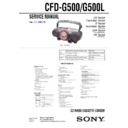
Sony CFD-G500 / CFD-G500L Service Manual ▷ View online
9
CFD-G500/G500L
3-8. H/P BOARD, TUNER BOARD
3-9. MAIN BOARD
9
H/P board
8
JACK HOLD board
3
Remove the soldering
4
TUNER board
1
two screws
(BVTP 3
(BVTP 3
×
10)
7
screws
(PWH 2.6
(PWH 2.6
×
10)
6
connector
(9p) (CNP391)
5
connector
(3p) (CNP394)
2
connector
(11p) (CNP1)
2
three screws
(BVTP 3
(BVTP 3
×
10)
8
MAIN board
6
connector
(2p) (open/close)
3
connector
(6p) (CNP303)
5
connector
(2p) (CNP804)
1
Remove the harnesses
in the direction of the arrow.
in the direction of the arrow.
7
flexible flat cable
(14 core) (CNP802)
4
flexible flat cable
(CNP805)
10
CFD-G500/G500L
3-10. CD BLOCK SECTION
3-11. TAPE MECHANISM DECK
1
four screws
(PWH 2.6
(PWH 2.6
×
10)
2
CD block section
5
tape mechanism deck
3
three screws
(BVTP 3
(BVTP 3
×
10)
1
connector
(6p) (CNP303)
2
flexible flat cable
(CNP805)
4
Open the cassette lid.
11
CFD-G500/G500L
3-12. TC BOARD
3-13. MAIN BELT, SUB BELT
2
hook
1
screw
3
Remove soldering from the four points.
yellow red gray
black
4
TC board
TC board
1
two screws
(+bind DT M2
(+bind DT M2
×
6)
3
pulley motor section
(M971)
(M971)
2
hook
4
main belt (B)
5
sub belt (B)
12
CFD-G500/G500L
SECTION 5
ELECTRICAL ADJUSTMENTS
SECTION 4
MECHANICAL ADJUSTMENTS
PRECAUTION
1. Clean the following parts with a denatured-alcohol-moistened
swab :
record/playback head
pinch roller
erase head
rubber belts
capstan
idlers
2. Demagnetize the record/playback head with a head
demagnetizer. (Do not bring the head magnetizer close to the
erase head.)
erase head.)
3. Do not use a magnetized screwdriver for the adjustments.
4. The adjustments should be performed with the rated power
4. The adjustments should be performed with the rated power
supply voltage (9V) unless otherwise noted.
Torque Measurement
Mode
Torque meter
Meter reading
2.95 – 6.86 mN • m
FWD
CQ-102C
(30 – 70 g • cm)
(0.42 – 0.97 oz • inch)
FWD
0.15 – 0.53 mN • m
Back Tension
CQ-102C
(1.5 – 5.5 g • cm)
(0.021 – 0.076 oz • inch)
more than 5.88 mN • m
FF
CQ-201B
(more than 60 g • cm)
(more than 0.83 oz • inch)
more than 5.88 mN • m
REW
CQ-201B
(more than 60 g • cm)
(more than 0.83 oz • inch)
Tape Tension Measurement
Mode
Torque meter
Meter reading
FWD
CQ-403A
more than 100 g
(more than 3.53 oz)
i
jack (J391)
set
32
Ω
test tape
WS-48A
(3 kHz, 0 dB)
WS-48A
(3 kHz, 0 dB)
digital frequency
counter
counter
TAPE SECTION 0 dB = 0.775 V
• Standard Output Level
Output terminal
HP OUT
load impedance
32
Ω
output signal level
0.25 V (–10 dB)
• Test Tape
Type
Signal
Used for
WS-48A
3 kHz, 0 dB
tape speed adjustment
Tape Speed Adjustment
Procedure:
Mode: playback
Adjust so that the value on the digital frequency counter is
3,000 Hz.
Mode: playback
Adjust so that the value on the digital frequency counter is
3,000 Hz.
Specification Value:
Digital frequency counter
2,940 to 3,060 Hz
Adjust so that the frequency at the beginning and that at the end of
tape winding are between 2,970 to 3,030 Hz.
tape winding are between 2,970 to 3,030 Hz.
Adjustment Location:
Tape speed adjustment
control inside motor
(M971)
control inside motor
(M971)
Click on the first or last page to see other CFD-G500 / CFD-G500L service manuals if exist.

