Sharp VC-M315HM (serv.man5) Service Manual ▷ View online
31
VC-M305HM/LM
VC-M315HM/LM
VC-M315HM/LM
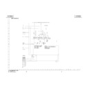
Measuring
instrument
instrument
Mode
Monitor Screen
EE
Specification
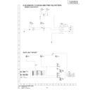
<On Screen Display>
Jumper List
Jumper List
On Screen Display confirm Display
Reference
Reference
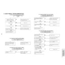
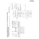
TIMER Circuit ADJUSTMENT
ADJUSTMENT OF Timer Initial JP and Y/C
Rec Current Confirmation
Rec Current Confirmation
Display eg:
JP :
0
0
3
4
3
0
0
0
1
4
HEX CODE for Initial Jumper
YC :
34
34
07
07
PAL
PAL
NTSC
NTSC
SP
LP/EP
SP
EP
VM : F8FB
←
Video Mode
NOR__
←
ROM Version
1. During EE mode, send the TEST Code (R/C code 47H)
to VCR and hold the Test code, do not let go.
2. While sending the TEST code, the monitor screen will
display the initial JP and Y/C Rec Current setting,
Video mode and ROM Version condition.
Video mode and ROM Version condition.
3. After confirmation, Release the TEST code (R/C code
47H), display will return to EE mode.
32
VC-M305HM/LM
VC-M315HM/LM
VC-M315HM/LM
Power Circuit ADJUSTMENT
ADJUSTMENT OF Output Voltage Confirm
ADJUSTMENT OF Over Load Characteristic
Confirmation
Confirmation
Item
Test point
Specification
Fix Load
AT 12V
AT between 12Vline~GND
Output above 11.0V 2.0~2.2A(over load)
AT 25V
AT between 25.5Vline~GND Output above 25.0V
Measuring
instrument
instrument
Oscilloscope
ADJUSTMENT OF Power Consumption Con-
firmation
firmation
Item
Test point
Specification Fix Load
AT 12V
AT between 12Vline~GND
DC 12.5V
±
0.3V
360mA+actual load
AT 5V
AT between 5Vline~GND
DC 5.25V
±
0.1V 18mA+actual load
AT 39V
AT between 39Vline~GND
DC 39.0V
±
2.0V actual load
AT 25V
AT between 25.5Vline~GND DC 26.0V
±
1.0V actual load
Measuring
instrument
instrument
Digital Voltmeter
<Setting Condition>
1. Power Supply : AC190V(50Hz)
2. Surroung temperature Setting : 20ºC
1. Power Supply : AC190V(50Hz)
2. Surroung temperature Setting : 20ºC
±
10ºC
3. Load connect place : between AT 5V
→
AC connector
8
PIN~AC connector
1
PIN
(High speed)
:
between
AT25.5V
→
AC
5
PIN~AC
2
PIN
(Other model)
:
between
AT12V
→
AC
5
PIN~AC
2
PIN
When apply the over load at the AT12V/AT25.5V output
for every 170msec, confirm that the output is 11.0V/25.0V
for every time.
for every 170msec, confirm that the output is 11.0V/25.0V
for every time.
70
100
2.2A
0.65A
(A)
(msec)
Measuring
instrument
instrument
Mode
Fix Load
Power Consumption device
Power off
actual load
Test point
AC Plug
Specification
3.0W MAX
1.Power supply : AC230V(50Hz)
2.Surround Temperature Setting : 20ºC
2.Surround Temperature Setting : 20ºC
±
10ºC
Display

