Sharp LC-46LE700E (serv.man6) Service Manual ▷ View online
LC-32/40/46LE700E/RU/S,LU700E/S,LX700E/RU,LC-52LE700E/RU/S
4 – 13
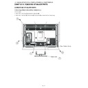
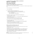
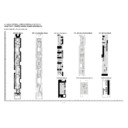
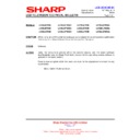
12. Handling notes (46 inch models).
1. Set and connect LED-PWBs.
2. Peel off the lamination film of LENS SHEET on the both sides.
RUNTKA595WJ01 / WJ02
RUNTKA596WJ01 / WJ02
RUNTKA598WJ01 / WJ02
㧨CAUTION㧪
It being alternated
RUNTKA***WJ01
and RUNTKA***WJ02.
RUNTKA***WJ01
and RUNTKA***WJ02.
Top Side
Bottom Side (C-PWB side)
RUNTKA***WJ01
RUNTKA***WJ02
RUNTKA***WJ01
RUNTKA***WJ02
RUNTKA***WJ01
RUNTKA***WJ02
RUNTKA***WJ01
RUNTKA***WJ02
RUNTKA***WJ01
RUNTKA***WJ02
RUNTKA***WJ01
*Same for other lines.
INSIDE of
BL-CHASSIS
Connect LED-PWBs
Set and connect LED-PWBs
Boss fitting
(showing in blue circles)
RUNTKA595WJ**
RUNTKA596WJ**
RUNTKA598WJ**
LED-PWB
Boss of
BL-CHASSIS
TERMINATOR
is Attached
WIRE HARNESS
LED-PWB set direction
(arrow mark to harness side)
(arrow mark to harness side)
LED-PWB set direction
(arrow mark to harness side)
(arrow mark to harness side)
LED-PWB set direction
(arrow mark to harness side)
(arrow mark to harness side)
Insert the connector horizontally mutually.
Do not add impossible power.
Do not add impossible power.
FRONT
BACK
Peel off the lamination film of LENS SHEET on the both sides.
Peel off the lamination film.
LC-32/40/46LE700E/RU/S,LU700E/S,LX700E/RU,LC-52LE700E/RU/S
4 – 14
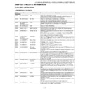
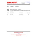
13. Removing of Bezel Ass’y, Panel Chassis Ass’y, Lens Sheet, Diffusion Plate, Back Light Chassis and LCD
Control Unit (52 inch models).
Control Unit (52 inch models).
NOTE: A clean booth is required for repair of the component units and/ or parts (LCD Panel HIRAKI, LED PWB etc.) inside the LCD panel module
unit.
1. Remove the 9 lock screws
, 3 lock screws
18 lock screws
and detach the Bezel Ass’y
.
2. Remove the 6 Clip
and detach the 52” LCD Panel Unit and Panel Chassis Ass’y
.
3. Detach the Optical Sheet
and Lens Sheet
and Diffusion Plate
.
4. Remove the 43 Push Rivets
and 11 Support Pins
and detach the Reflection Sheet
.
5. Remove the 72 Push Rivets
.
6. Remove the 12 Terminators
and 24 connections
and detach the 12 LED8 PWB1 Units
and 12 LED8 PWB2 Units
.
7. Detach the 6 LED6 PWB1 Units
and 6 LED6 PWB2 Units
.
8. Disconnect the connecting cords from the 12 connectors
of the LED6 PWB1/2 Unit.
9. Detach the Back Light Chassis
.
10.Detach the 2 Connecting Cord
and 2 Ferrite Core
.
11.Remove the 6 lock screws
and detach the LCD Control Unit
䎕䎓
䎔
䎖
䎕
䎘
䎗
䎙
䎛
䎜
䎔䎔
䎔䎖
䎔䎜
䎔䎛
䎔䎚
䎔䎘
䎔䎙
䎔䎚
䎕䎔
䎕䎕
䎕䎖
䎘䎕䎅䎃䎯䎦䎧
䎳䏄䏑䏈䏏䎃䎃䎸䏑䏌䏗
䎳䏄䏑䏈䏏䎃䎃䎸䏑䏌䏗
䎥䏈䏝䏈䏏䎃䎃䎤䏖䏖䎊䏜
䎳䏄䏑䏈䏏䎃䎃䎦䏋䏄䏖䏖䏌䏖䎃
䎤䏖䏖䎊䏜
䎤䏖䏖䎊䏜
䎯䏈䏑䏖䎃䎶䏋䏈䏈䏗
䎚
䎲䏓䏗䏌䏆䏄䏏䎃䎶䏋䏈䏈䏗
䎧䏌䏉䏉䏘䏖䏌䏒䏑䎃䎳䏏䏄䏗䏈
䎥䏄䏆䏎䎃䎯䏌䏊䏋䏗䎃
䎦䏋䏄䏖䏖䏌䏖
䎦䏋䏄䏖䏖䏌䏖
䎩䏈䏕䏕䏌䏗䏈
䎦䏒䏕䏈
䎦䏒䏕䏈
䎦䏒䏑䏑䏈䏆䏗䏌䏑䏊䎃䎦䏒䏕䏇
䎯䎦䎧䎃䎦䏒䏑䏗䏕䏒䏏䎃
䎃䎸䏑䏌䏗
䎃䎸䏑䏌䏗
䎦䏏䏌䏓
䎵䏈䏉䏏䏈䏆䏗䏌䏒䏑䎃䎶䏋䏈䏈䏗
䎶䏘䏓䏓䏒䏕䏗䎃䎳䏌䏑
䎳䏘䏖䏋䎃䎵䏌䏙䏈䏗
䎕䎘
䎕䎗
䎔䎓
䎔䎕
䎔䎘
䎔䎙
䎔䎗
LC-32/40/46LE700E/RU/S,LU700E/S,LX700E/RU,LC-52LE700E/RU/S
4 – 15
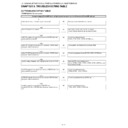
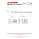
14. Handling notes (52 inch models).
1. Set and connect LED-PWBs.
2. Peel off the lamination film of LENS SHEET on the both sides.
RUNTKA596WJ01 / WJ02
RUNTKA598WJ01 / WJ02
Top Side
Bottom Side (C-PWB side)
RUNTKA***WJ01
RUNTKA***WJ02
RUNTKA***WJ01
RUNTKA***WJ02
RUNTKA***WJ01
RUNTKA***WJ02
RUNTKA***WJ01
RUNTKA***WJ02
RUNTKA***WJ01
RUNTKA***WJ02
RUNTKA***WJ01
RUNTKA***WJ02
*Same on the other line.
Set and connect LED-PWBs
Boss fitting
(showing in blue circles
LED-PWB
Boss of
BL-CHASSIS
TERMINATOR
˴is Attached
RUNTKA596WJ**
RUNTKA598WJ**
<Reference>
The insertion process of the LED6-PWB(1&2) and LED8-PWB(1&2)
㧨CAUTION㧪
It being alternated
RUNTKA***WJ01
and RUNTKA***WJ02.
and RUNTKA***WJ02.
RUNTKA598WJ01 / WJ02
and TERMINATOR
RUNTKA596WJ01 / WJ02
RUNTKA598WJ01 / WJ02
RUNTKA598WJ01 / WJ02
and TERMINATOR
LED-PWB set direction
(arrow mark to harness side)
(arrow mark to harness side)
LED-PWB set direction
(arrow mark to harness side)
(arrow mark to harness side)
Insert the connector horizontally mutually.
Do not add impossible power.
Do not add impossible power.
LED-PWB set direction
(arrow mark to harness side)
(arrow mark to harness side)
Ionized air blowers
blowing way
blowing way
FRONT
BACK
Peel off the lamination film of LENS SHEET on the both sides.
Peel off the lamination film.
LC-32/40/46LE700E/RU/S,LU700E/S,LX700E/RU,LC-52LE700E/RU/S
4 – 16
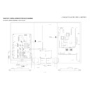
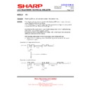
15. Handling notes
Please note the following handling notes enough, when this product is used.
Moreover, please execute an enough evaluation (temperature rise and I/F match, etc.) and confirmations while installed in your product.
1. Since this product uses LED (light emitting diode). note the static electricity at handling, and do the countermeasure against static electricity of the
body grounding etc.
2. Please do not give the stress by the fall, the impact, and the accumulation of product etc. when you handle the product.
3. The installation hole must be fixed at grade, and stresses such as “Warp” and “Twist” must not join the board when you install the board. Moreover,
please do not work with the part LED, the diffusion lens, and the reflection sheet.
Please do not touch by the hand with the bord..the bar code and the serial number part...
* Otherwise, it causes scratches/dirt adhesion.
4. Please put in parallel to the connector and horizontally, and insert it in the interior surely when you insert the connector. Moreover, please use
gloves, etc. not to touch the connector terminal directory by bare-handed.
5. Please turn off the power supply and the signal input to the board unit surely, when this product is inserted in or removes from the connector.
* Otherwise, it causes the part damage.
7. When the LED unit is handling and built into the equipment, long-term storage in the oxidation or reduced gas atmosphere or the use of use of
materials such as the reagent that generates these steams of the oxidation or reduced gas, the solvent, adhesives, and resins might cause corro-
sion and discoloration.
sion and discoloration.
8. Time between turning on power and stabilizing brightness and Chromaticity. : 5min (60mA, at 25
°C).

