Sharp LC-46DH66 (serv.man5) Service Manual ▷ View online
LC-46DH65E/S, LC-46DH66E
4 – 13
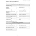
<During external connection> No picture on the monitor (3)
No picture from EXT1 appears on EXT2-connected monitor.
Is CVBS signal output into pin (19) of EXT2 (SC501)?
YES
Check the setting of an external input device that connects with
EXT2.
EXT2.
NO
Is CVBS signal output to pin (65) of IC503?
YES
Check the line between IC503 and EXT2 (SC501).
NO
Is CVBS signal sent to pin (100) of IC503?
YES
Check the IC503 and peripheral circuits.
NO
YES
Is the I2C SERIAL DATA/CLOCK communication normal?
Pin32: SDA1/Pin31: SCL1
Pin32: SDA1/Pin31: SCL1
Is CVBS signal sent to pin (20) of EXT1(SC502)?
YES
Check the line between EXT1(SC502) and IC503.
NO
Check the setting of an external input device that connects with
EXT1.
EXT1.
<During external connection> No picture on the monitor (4)
SCART2:
No picture from EXT8 appears on EXT2- connected monitor.
No picture from EXT8 appears on EXT2- connected monitor.
Is CVBS signal output into pin(19) of EXT2 (SC501)?
YES
Check the setting of an external input device that connects with
EXT2.
EXT2.
NO
Is CVBS signal output to pin (65) of IC503?
YES
Check the line between IC503 and EXT2(SC501).
NO
Is CVBS signal sent to pin (12) of IC503?
YES
Check the IC503 and peripheral circuits.
NO
Is CVBS signal sent to pin (6) of EXT8(J505)?
YES
Check the line between EXT8(J505) and IC503.
YES
Check the setting of an external input device that connects with
EXT8.
EXT8.
NO
Is V3_PLUGl detection signal to pin(13) of IC503 input from
pin(7) of EXT8 (J505)?
pin(7) of EXT8 (J505)?
LC-46DH65E/S, LC-46DH66E
4 – 14
[2] LED flashing specification at the time of the error
Display method
• Refer to Table 1.
• Make the OPC LED flash using the [MENU] key on the remote control since the display for service persons is identified by the number of flashings
(once to 5 times).
Even if the [MENU] key is pressed again, it does not return to the display for customers (only the power LED flashes).
• After recovering from an error, if the same error cannot be generated again, refer to MONITOR ERR CAUSE on the adjustment process screen.
LED flashing method
• Synchronize the phases of the power LED and OPC LED.
• If the LEDs have different number of flashings, adjust the flashing cycle to that where the LED flashes more times.
Table 1. Concrete flashing pattern
* 1: For details, refer to ERROR STANDBY CAUSE on the adjustment process screen.
* 2: If the boot section is abnormal, there is no flashing (flashing disabled).
Item
For customers
For service persons
Cause
Power
OPC
Power
OPC
Inverter/Lamp system failure
Red flashes once
Off
Red flashes once
Flashes once
Lamp error
Power PWB failure (Power
failure, etc.)
failure, etc.)
Red flashes twice
Off
Red flashes twice
Flashes once
AC_DET error
Flashes twice
UR+13.5V error
Flashes 3 times
D3.3V error
Flashes 5 times
Panel power supply error
Main PWB failure
Green flashes once
Off
Green flashes once
Flashes once
Initial communication error
(Communication failure, etc.)
Flashes twice
Start-up confirmation commu-
nication error
nication error
Flashes 3 times
Regular communication error
Flashes 5 times
Other communication error
Others
Green flashes twice
Off
Green flashes twice
Flashes once
Temperature error
Flashes twice
Sync error
Flashes 3 times
Notification from the main
microprocessor (*1)
microprocessor (*1)
VerUP executing
Orange flashes once
Off
Orange flashes once Off
Version upgrading
VerUP succeeded
Power green/OPC flash alternately
Power green/OPC flash alternately
Version upgrade succeeded
VerUP failed
Green/Red flash
alternately
alternately
Off
Green/Red flash
alternately
alternately
Off
Version upgrade failed
System
Red flashes 3 times
Off
Red flashes 3 times
Off
Mounting discrimination con-
nector unplugged
nector unplugged
ROM data failure
Green/Red flash
alternately
alternately
Off
Green/Red flash
alternately
alternately
Off
Start-up after failing version
upgrade (*2)
upgrade (*2)
<Flashing example for customers>
Power
<Flashing example for service persons>
Power
OPC
(Displayed by the
specific operation)
(Displayed by the
specific operation)
300ms
300ms
1500ms
300ms
1500ms
300ms
LC-46DH65E/S, LC-46DH66E
4 – 15
MONITOR ERR STBY table
LED flashing timing chart at the time of the error
1) Power LED
Outline:
Communication/Power failure detected by the monitor microprocessor (IC2003) is stored on EEPROM, and the last 4 abnormal
states can be confirmed in the adjustment process mode.
states can be confirmed in the adjustment process mode.
Location:
Page 1/16 of the adjustment process mode: MONITOR ERR CAUSE
"0" if there is no error. It is cleared to 0 on the last page of the adjustment process mode.
"0" if there is no error. It is cleared to 0 on the last page of the adjustment process mode.
Display
Error description
02
Start-up communication error 2
Initial communication from the main CPU is not received.
03
Start-up communication error 3
Only the initial communication is received.
04
Start-up communication error 4
Until panel information request reception
05
Start-up communication error 5
Until initialization completion reception
06
Start-up communication error 6
Until version notification transmission
07
Start-up communication error 7
Until start-up information notification transmission
08
Start-up communication error 8
Until start-up information response reception
09
Start-up communication error 9
Until time-out setting reception
0A
Communication error A
REQ time-out
0B
Communication error B
Restart time-out during the beginning of time acquisition start-up
0C
Communication error C
Ending sequence time-out
0D
Communication error D
Preset start-up time-out during completion
0E
Communication error E
Download start-up time-out
0F
Communication error F
Time acquisition time-out
11
Communication error H
Regular communication time-out
16
Panel-related error
Lamp failure
1A
Other error 2
Monitor temperature failure
1D
Power supply error 1
PS_ON(AC_DET) failure
1E
Power supply error 2
D_POW(DET_12V) failure
1F
Power supply error 3
D_POW(DET_D3V3) failure
21
Power supply error 5
Panel power failure
23
Other error 3
Error standby request from the main CPU
Error type
Power LED operation (1 cycle)
Note: Pins are monitor microprocessor pins (IC2003).
Inverter/Lamp fail-
ure
Red flashes once
ure
Red flashes once
H: Red on
Refer to "Inverter/Lamp failure details". OPC_LED flashes by pressing the
[MENU] key on the remote control.
[MENU] key on the remote control.
L: Off
Power failure
Red flashes twice
Red flashes twice
H: Red on
Refer to "Power failure details". OPC_LED flashes by pressing the [MENU]
key on the remote control.
key on the remote control.
L: Off
Communication
failure with main
CPU
Green flashes
once
failure with main
CPU
Green flashes
once
H: Green on
Refer to "Communication failure details". OPC_LED flashes by pressing the
[MENU] key on the remote control.
Communication line failure or main CPU communication failure.
[MENU] key on the remote control.
Communication line failure or main CPU communication failure.
L: Off
Others
Green flashes
twice
Green flashes
twice
H: Green on
Refer to "Other failure details". OPC_LED flashes by pressing the [MENU]
key on the remote control.
key on the remote control.
L: Off
300m
s
1.5sec
LC-46DH65E/S, LC-46DH66E
4 – 16
2) Inverter/Lamp failure details (Power red LED flashes once and OPC (preset) LED flashes)
3) Power failure details (Power red LED flashes twice and OPC (preset) LED flashes)
4) Communication failure details (Power green LED flashes once and OPC (preset) LED flashes)
5) Other failure details (Power green LED flashes twice and OPC (preset) LED flashes)
Error type
OPC (preset) LED operation (1 cycle)
Lamp failure
Flashes once
Flashes once
H: On
ERR_PNL(40pin): Abnormal L. Confirmed after 5 consecutive detections at 1 second
intervals (detected only when the backlight is on).
Note that after five detection counts, the lamp cannot be activated except in the moni-
toring process. (For the first time, only the inverter is reset, and error OFF is not acti-
vated.)
Accumulated counts are cleared to 0 when the setting in the adjustment process is
made, when AC_ON is performed with [CH_DOWN] and [VOL_UP] on the unit down
or after continuous illumination for 3 minutes.
L: Off
Error type
OPC (preset) LED operation (1 cycle)
PS_ON
AC_DET fail-
ure Flashes
once
AC_DET fail-
ure Flashes
once
H: On
AC_DET(72pin: Abnormal (L).
If error is detected during start-up or operation, the power is turned on again by inter-
rupt handling (instantaneous blackout processing).
If error is detected during start-up or operation, the power is turned on again by inter-
rupt handling (instantaneous blackout processing).
L: Off
D_POW
Main 12V fail-
ure Flashes
twice
Main 12V fail-
ure Flashes
twice
H: On
DET_12V(34pin): Abnormal (L). Main 12V is not applied.
L: Off
If error is detected during start-up or operation, the power is turned on again by polling.
D_POW
Digital 3.3V
Failure
Flashes 3
times
Digital 3.3V
Failure
Flashes 3
times
H: On
DET_D3V3(35pin): abnormal (L). Digital 3.3V is not applied.
L: Off
If error is detected during start-up or operation, the power is turned on again by polling.
Error type
OPC (preset) LED operation (1 cycle)
Note: Basically, debug print logs are analyzed or communication logs
are analyzed by a bus monitor.
are analyzed by a bus monitor.
Initial communi-
cation reception
failure Flashes
once
cation reception
failure Flashes
once
H: On
Initial communication from the main CPU is not received. (Request for the
monitor model No. is not received.)
→ Communication line failure or main CPU start-up failure
monitor model No. is not received.)
→ Communication line failure or main CPU start-up failure
L: Off
Start-up confir-
mation recep-
tion failure
Flashes twice
mation recep-
tion failure
Flashes twice
H: On
Start-up reason confirmation from the main CPU cannot be received. (Start-
up communication until start-up reason notification command is not
received.)
→ Main CPU start-up failure or monitor microprocessor reception failure
up communication until start-up reason notification command is not
received.)
→ Main CPU start-up failure or monitor microprocessor reception failure
L: Off
Regular commu-
nication failure
Flashes 3 times
nication failure
Flashes 3 times
H: On
Regular communication that is performed at 1 second intervals in the nor-
mal operation is interrupted.
→ Main CPU operation failure or monitor microprocessor reception failure
mal operation is interrupted.
→ Main CPU operation failure or monitor microprocessor reception failure
L: Off
Other communi-
cation failure
Flashes 5 times
cation failure
Flashes 5 times
H: On
When a request (PM_REQ=H) is sent from the main microprocessor, the
request command is not output from the main CPU, etc.
→ Main CPU operation failure or monitor microprocessor reception failure
request command is not output from the main CPU, etc.
→ Main CPU operation failure or monitor microprocessor reception failure
L: Off
Error type
OPC (preset) LED operation (1 cycle)
Monitor temper-
ature failure
Flashes once
ature failure
Flashes once
H: On
If the panel temperature is 60
°C or more for 15 seconds or more in a row, CAUTION
appears on the OSD (flashes in red in the lower right screen).
If the panel temperature is 60
If the panel temperature is 60
°C or more for 25 seconds or more in a row, error
standby is activated.
(MONITOR MAX TEMP on page 13/16 of the adjustment process: Change of tem-
perature failure AD value): Thermistor
(MONITOR MAX TEMP on page 13/16 of the adjustment process: Change of tem-
perature failure AD value): Thermistor
L: Off
Main failure
Flashes 3 times
Flashes 3 times
H: On
Main microprocessor detection error (CPU temperature error, etc.)
Details are displayed on page 1/16 of the adjustment process for the main micropro-
cessor.
Details are displayed on page 1/16 of the adjustment process for the main micropro-
cessor.
L: Off

