Sharp LC-42XD1EA (serv.man4) Service Manual ▷ View online
LC-42XD1EA/RUA
4 – 17
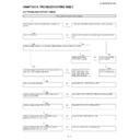
<When EXT5 is used for external input> No picture on the display (7)
No EXT5 (HDMI) output of the external input system.
Checklist:
1) Is “INPUT SOURCE” button
on the remote control set up correctly? ... See the operation manual and set “INPUT SOURCE” to “EXT5”.
2) Have you checked the type video signal sent from HDMI-connected external device? ... Confirm the type (it should “RGB”, “YCbCr 4:4:4” or
“YCbCr 4:2:2”).
3) Have you checked the type of Color matrix sent from HDMI-connected external device? ... Confirm the type (it should be “ITU601” or “ITU709”.)
4) Is ANT-CABLE disconnected or connected improperly? ... Connect it correctly as per the operation manual
4) Is ANT-CABLE disconnected or connected improperly? ... Connect it correctly as per the operation manual
Is “EXT5” selected with
button on the remote control?
NO
Select “EXT5” with
button on the remote control.
YES
Is the type of video signal (Signal Type) from HDMI- connected
external device set?
external device set?
NO
From MENU-Connections-HDMI setup-EXT5-Signal type, select a
signal type
(“RGB”, “YCbCr 4:4:4” or “YCbCr 4:2:2”)
signal type
(“RGB”, “YCbCr 4:4:4” or “YCbCr 4:2:2”)
YES
Is the type of color signal (Color matrix) from HDMI -connected
external device set?
external device set?
NO
From MENU-Connections-HDMI setup-EXT5-Color Matrix, select a
color signal type (“ITU601” or “ITU709”)
color signal type (“ITU601” or “ITU709”)
YES
Is TMDS signal (RX*
±signal) sent to pins (1) - (12) of
EXT5 (HDMI) terminal (SC1901)?
NO
Is I2C signal (SDA/SCL signal) sent to pins (16) and (15) of EXT5
(HDMI) terminal? Check external connection and peripheral circuits.
(HDMI) terminal? Check external connection and peripheral circuits.
YES
Is 8bit-DIGITAL signal (HDMI- R/G/B) sent from pins (110)-
(144) of IC1905 (HDMI-RECEIVER)?
(144) of IC1905 (HDMI-RECEIVER)?
NO
Check power supply (3.3/1.8V) pins (99) and (74) of IC1905,
SDA/SCL signal pins (29) and (30), and peripheral circuits.
SDA/SCL signal pins (29) and (30), and peripheral circuits.
YES
Is 8bit-DIGITAL signal (HDMI- R/G/B) sent to pins (B10) -
(D15) of IC3002 (V-PRO.)?
(D15) of IC3002 (V-PRO.)?
NO
Check SDA3/SCL3 signal pins (27) and (28), interface between
IC1905 and lC3002, and peripheral circuits.
IC1905 and lC3002, and peripheral circuits.
YES
Is LVDS video signal (TA1
± - TD1±) sent to pins (AB8)/(AC8) - (AB3)/(AC3) of IC3002 (V-PRO.), and is
CLK signal (CK1
±) sent to pins (AB5)/(AC5)?
Is LVDS video signal (TA2
± - TD2±) sent to pins (AC2)/(AC1) - (V2)/(V1) of IC3002 (V-PRO.), and is
CLK signal (CK2
±) sent to pins (Y2)/(Y1)?
NO
Check pins (G14)/(U10) of
BU3.3V line of IC3002 (V-
PRO.), pins (G10)/(N17) of
BU2.5V line, pins (U16)/
(G12) of BU1.8V line and
peripheral circuits.
BU3.3V line of IC3002 (V-
PRO.), pins (G10)/(N17) of
BU2.5V line, pins (U16)/
(G12) of BU1.8V line and
peripheral circuits.
YES
Is LVDS video signal (TA1
± - TD1±) sent to pins (3)/(2) -(12)/(11) of CONNECTOR CN1 of LCD-CONT-
UNIT, and is CLK signal (CK1
±) sent to pins (10)/(9)?
Is LVDS video signal (TA2
± - TD2±) sent to pins (17)/(16) -(26)/(25) of CONNECTOR CN1 of LCD-
CONT-UNIT, and is CLK signal (CK2
±) sent to pins (24)/(23)?
NO
Check CONNECTOR
(SC2302, CN1) and HAR-
NESS WIRE (LV).
(SC2302, CN1) and HAR-
NESS WIRE (LV).
YES
Is power (+12V) supplied to pins (1) - (5) of CONNECTOR CN2 in LCD-CONT-UNIT?
NO
Check CONNECTOR
(CN2,P707) and HARNESS
WIRE (PL).
(CN2,P707) and HARNESS
WIRE (PL).
YES
Replace LCD-CONT-UNIT.
LC-42XD1EA/RUA
4 – 18
<When EXT6 is used for external input> No picture on the display (8)
No EXT6 (HDMI) output of the external input system.
Checklist:
1) Is “INPUT SOURCE” button
on the remote control set up correctly? ... See the operation manual and set “INPUT SOURCE” to “EXT6”.
2) Have you checked the type video signal sent from HDMI-connected external device? ... Confirm the type (it should “RGB”, “YCbCr 4:4:4” or
“YCbCr 4:2:2”).
3) Have you checked the type of Color matrix sent from HDMI-connected external device? ... Confirm the type (it should be “ITU601” or “ITU709”.)
4) Is ANT-CABLE disconnected or connected improperly? ... Connect it correctly as per the operation manual.
4) Is ANT-CABLE disconnected or connected improperly? ... Connect it correctly as per the operation manual.
Is “EXT6” selected with
button on the remote control?
NO
Select “EXT6” with
button on the remote control.
YES
Is the type of video signal (Signal Type) from HDMI- connected
external device set?
external device set?
NO
From MENU-Connections-HDMI setup-EXT6-Signal type, select a
signal type (“RGB”, “YCbCr 4:4:4” or “YCbCr 4:2:2”)
signal type (“RGB”, “YCbCr 4:4:4” or “YCbCr 4:2:2”)
YES
Is the type of color signal (Color matrix) from HDMI -connected
external device set?
external device set?
NO
From MENU-Connections-HDMI setup-EXT6-Color Matrix, select a
color signal type (“ITU601” or “ITU709”)
color signal type (“ITU601” or “ITU709”)
YES
Is TMDS signal (RX*
±signal) sent to pins (1) - (12) of EXT6
(HDMI) terminal (SC1902)?
NO
Is I2C signal (SDA/SCL signal) sent to pins (16) and (15) of EXT6
(HDMI) terminal? Check external connection and peripheral cir-
cuits.
(HDMI) terminal? Check external connection and peripheral cir-
cuits.
YES
Is 8bit-DIGITAL signal (HDMI- R/G/B) sent from pins (110)-
(144) of IC1905 (HDMI-RECEIVER)?
(144) of IC1905 (HDMI-RECEIVER)?
NO
Check power supply (3.3/1.8V) pins (99) and (74) of IC1905,
SDA/SCL signal pins (29) and (30), and peripheral circuits.
SDA/SCL signal pins (29) and (30), and peripheral circuits.
YES
Is 8bit-DIGITAL signal (HDMI- R/G/B) sent to pins (B10) - (D15)
of IC3002 (V-PRO.)?
of IC3002 (V-PRO.)?
NO
Check SDA3/SCL3 signal pins (27) and (28), interface between
IC1905 and lC3002, and peripheral circuits.
IC1905 and lC3002, and peripheral circuits.
YES
Is LVDS video signal (TA1
± - TD1±) sent to pins (AB8)/(AC8) -
(AB3)/(AC3) of IC3002 (V-PRO.), and is CLK signal (CK1
±)
sent to pins (AB5)/(AC5)?
Is LVDS video signal (TA2
Is LVDS video signal (TA2
± - TD2±) sent to pins (AC2)/(AC1) -
(V2)/(V1) of IC3002 (V-PRO.), and is CLK signal (CK2
±) sent to
pins (Y2)/(Y1)?
NO
Check pins (G14)/(U10) of BU3.3V line of IC3002 (V-PRO.), pins
(G10)/(N17) of BU2.5V line, pins (U16)/(G12) of BU1.8V line and
peripheral circuits.
(G10)/(N17) of BU2.5V line, pins (U16)/(G12) of BU1.8V line and
peripheral circuits.
YES
Is LVDS video signal (TA1
± - TD1±) sent to pins (3)/(2) -(12)/(11) of CONNECTOR CN1 of LCD-
CONT-UNIT, and is CLK signal (CK1
±) sent to pins (10)/(9)?
Is LVDS video signal (TA2
± - TD2±) sent to pins (17)/(16) -(26)/(25) of CONNECTOR CN1 of LCD-
CONT-UNIT, and is CLK signal (CK2
±) sent to pins (24)/(23)?
NO
Check CONNECTOR
(SC2302, CN1) and
HARNESS WIRE (LV).
(SC2302, CN1) and
HARNESS WIRE (LV).
YES
Is power (+12V) supplied to pins (1) - (5) of CONNECTOR CN2 in LCD-CONT-UNIT?
NO
Check CONNECTOR (CN2,
P707) and HARNESS WIRE
(PL).
P707) and HARNESS WIRE
(PL).
YES
Replace LCD-CONT-UNIT.
LC-42XD1EA/RUA
4 – 19
FRC circuit failure
Note: The SD signal (576i 480i) alone passes through the FRC circuit. (The HD signal does not go through.)
Does the image appear with the HD sig-
nal, but not with the SD signal?
nal, but not with the SD signal?
Does anything unusual (which or black-
ish screen, block noise, for example)
appear on the screen?
ish screen, block noise, for example)
appear on the screen?
Does the image look unusual with the
power switch turned on?
power switch turned on?
YES
YES
YES
Is the power supplied to IC3301 (FRC)?
Is there the FRC-IN signal input at pins
(142) and (13) of IC3301?
Check the soldering condition.
Is there the FRC-IN signal input at pins
(142) and (13) of IC3301?
Check the soldering condition.
Is there the specified RESET-A signal
input at pin (39) of IC3301 (FRC)?
(60 ms delay design)
input at pin (39) of IC3301 (FRC)?
(60 ms delay design)
Check the connection between pin
(R22) of IC3002 (V-PRO.) and pin
(142) of IC3301 (FRC) as well as that
between pin (N20) of IC3302 and pin
(13) of IC3301
(R22) of IC3002 (V-PRO.) and pin
(142) of IC3301 (FRC) as well as that
between pin (N20) of IC3302 and pin
(13) of IC3301
YES
NO
Replace IC3301 (FRC).
Check “RESET-A” signal pin (34) of
IC1710 (FPGA).
IC1710 (FPGA).
Backlight failure to light up
Do all the fluorescent tubes light up?
NO
Check the individual fluorescent
tubes for light-up failure.
tubes for light-up failure.
YES
Replace any defective fluorescent
tubes with new ones.
tubes with new ones.
YES
Is the power supplied to CN7501 on
the inverter unit?
the inverter unit?
NO
Check the connection between power
unit and inverter unit.
unit and inverter unit.
YES
Is the fuse (F7501 or F7502) in the
inverter unit circuit functioning?
inverter unit circuit functioning?
NO
Replace the blown-out fuse (F7501 or
F7502) on the inverter unit. Turn on
the power again.
If the fuse gets blown out again,
check the short-circuited spot.
F7502) on the inverter unit. Turn on
the power again.
If the fuse gets blown out again,
check the short-circuited spot.
YES
Check the transformer (T7501-T7511,
T7601-T7606) and their peripheral cir-
cuits as well as IC7501 and their
peripheral circuits.
T7601-T7606) and their peripheral cir-
cuits as well as IC7501 and their
peripheral circuits.
YES
Is the VCC power supplied to the
control IC (IC7501) on the inverter
unit?
control IC (IC7501) on the inverter
unit?
NO
Check the circuit connected with the
VCC terminal on the inverter control
IC (IC7501).
VCC terminal on the inverter control
IC (IC7501).
YES
Has each control signal come to
CN7502(LB)?
(OFL,OSC,STB)
CN7502(LB)?
(OFL,OSC,STB)
NO
Have the OFL,OSC and STB signal
come to P1701(LB) in the MAIN sub-
strate?
come to P1701(LB) in the MAIN sub-
strate?
NO
Check pins (19),(17) and (89) of
IC1710 (main PWB).
IC1710 (main PWB).
YES
Is the specified control signal input-
ted at IC7501 (INV-CTL) on the
inverter unit.
ted at IC7501 (INV-CTL) on the
inverter unit.
NO
Check the line between CN7502 and
IC7501.
IC7501.
YES
Are the Q7501 and Q7502 transis-
ters at the primary side of T7501
functioning?
ters at the primary side of T7501
functioning?
NO
Check the power line of IC7501, its
peripheral circuits or replace IC7501.
peripheral circuits or replace IC7501.
YES
Is the secondary circuit of T7501
functioning.
functioning.
NO
Replace T7501 or the T*** trans-
former for the fluorescent tubes, or
check their peripheral circuits.
former for the fluorescent tubes, or
check their peripheral circuits.
LC-42XD1EA/RUA
4 – 20
LCD failure 1
Does a single or several verti-
cal stripes appear on the LCD
screen?
cal stripes appear on the LCD
screen?
Does a single or several hori-
zontal stripes appear on the
LCD screen?
zontal stripes appear on the
LCD screen?
Do luminescent or black dots
appear on the screen?
appear on the screen?
Is the on-screen image rip-
pling or distorted?
pling or distorted?
Replace the LCD panel.
LCD failure 2
The backlight func-
tions. Does not the
image come out in the
LCD screen
(screen black)?
tions. Does not the
image come out in the
LCD screen
(screen black)?
Does the entire LCD
screen look whitish all
over?
screen look whitish all
over?
Does the QS drive func-
tion?
tion?
Are the data bit drop-
out?
(No solution even when
turning on and off the QS
drive)
out?
(No solution even when
turning on and off the QS
drive)
Is the gamma correc-
tion as specified?
tion as specified?
Replace the LCD control unit.

