Sharp LC-32LE600E (serv.man6) Service Manual ▷ View online
LC-32/40/46LE600E/RU/S
4 – 9
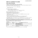
11. QS Temperature NVM Data Confirmation
During servicing of the LCD TV set, by software upgrading or by any cleaning NVM, it’s mandatory select the “INCH SIZE” in Service Mode, Page 1,
according to the size of the TV set.
according to the size of the TV set.
12. Initialization to factory settings
After a factory setting, It ends with the AC power supply OFF.
After a factory settings, Do not turn on the power supply. If you turn on the power supply. execute the factory settings again.
Do not do power supply OFF by remote control.
CAUTION: When the factory settings have been made, all user setting data, including the channel settings, are initialized.
(The adjustments done in the adjustment process mode are not initialized.) Keep this in mind when initializing these settings.
Adjustment item
Adjustment conditions
Adjustment procedure
1
Factory settings
Ends in AC power supply
OFF. (See to below caution)
OFF. (See to below caution)
[Factory setting with adjustment process mode]
• Enter the adjustment process mode.
• Move the cursor to “INDUSTRY INIT” on page 2/8.
• Use the / key of R/C to select a region from “YES (E)/YES (I)/YES (F)/YES (R)”
• Enter the adjustment process mode.
• Move the cursor to “INDUSTRY INIT” on page 2/8.
• Use the / key of R/C to select a region from “YES (E)/YES (I)/YES (F)/YES (R)”
and press the [OK] key.
• “EXECUTING” display appears and initialization starts.
• After a while, “OK” display appears, the setting is completed.
When succeeding: The background color becomes green.
When failing: The background color becomes red.
• After a while, “OK” display appears, the setting is completed.
When succeeding: The background color becomes green.
When failing: The background color becomes red.
NOTE: Never turn the power off during initialization.
When performing factory settings (while displaying page 2 of adjustment process), confirm
that the item “INCH SIZE” or the panel size displayed in the upper right corner corresponds
to each panel size.
The following items are initialized in the factory setting.
1) User settings
2) Channel data (e.g. broadcast frequencies)
3) Manufacturer option setting
4) Password data
After adjustments, exit the adjustment process mode.
To exit the adjustment process mode, turn off the MAIN power key.
When the power is turned off with the remote control, unplug the AC power cord and plug it back in.
(wait approximately 10 seconds before plugging in the AC power cord)
To exit the adjustment process mode, turn off the MAIN power key.
When the power is turned off with the remote control, unplug the AC power cord and plug it back in.
(wait approximately 10 seconds before plugging in the AC power cord)
Default picture after cleaning NVM.
Picture with [Inch Setting] to 32.
䋨It is actually set as each inch.䋩
PAGE
1/8
TV
32E_LE600E
㵘 M
ain
Version
-
Boot Version
-
T-CON Version
-
INCH SIZE
-
ERROR RESET
NO
STANDBY CAUSE 00 00 00 00 00
1) 00H 00M
PAGE
1/8
TV
32E_LE600E
㵘 M
ain
Version
-
Boot Version
-
T-CON Version
-
CPLD Version
-
CPLD Version
-
INCH SIZE
32
ERROR RESET
NO
STANDBY CAUSE 00 00 00 00 00
1) 00H 00M
LC-32/40/46LE600E/RU/S
4 – 10
13. Functional explanation of STANDBY CAUSE
13.1. [display method]
It is displayed in the top page of the process adjustment mode. (Page displayed first when entering process mode)
13.2. [Content of display]
1. NORMAL STANDBY CAUSE
The reason that became a power-off by the specification of usual use and the main body is displayed.
(Only the one latest) It is not displayed when power supply OFF is carried out with remote control.
2. ERROR STANDBY CAUSE
When main CPU becomes a power-off detecting some abnormalities, the use time of the set at the time of the reason and the power-off is dis-
played five times.
played five times.
When time information can be acquired from digital broadcasting, the date and time when the error occurs at the same time is recorded, displayed
and when time information cannot be acquired, it becomes the above-mentioned display.
and when time information cannot be acquired, it becomes the above-mentioned display.
“00” is displayed when abnormality has not been detected even once.
14. Lamp error detection
1. Function description
This LCD colour television has a function (lamp error detection) to be turned OFF automatically for safety when the lamp or lamp circuit is abnor-
mal.
mal.
If the lamp or lamp circuit is abnormal, or some other errors happen, and the lamp error detection is executed, the following occur.
1) The main unit of television is turned OFF about 5 seconds after it is turned ON.
(The power LED on the front side of TV turns from green to red.)
2) If the situation “1” happens 5 times sequentially, the power is turned on (relay is turned ON).
However, the backlight is not turned on, and then the relay is turned OFF after 5 to 6 seconds. (The power LED remains red.)
2. Countermeasures
When television is turned OFF by the lamp error detection mentioned above, it enters the adjustment process with the power LED red.
Entering the adjustment process, turns OFF the error detection and turns ON TV.
This enables the operation check to detect errors in the lamp or lamp circuit.
Check whether “STANDBY CAUSE” on line 7, page 1/8 of the adjustment process is “1B”. it indicates the lamp error detection was executed.
After confirming that the lamp or lamp circuit is normal, reset the lamp error counter pushing “OK” in the R/C.
After resetting counter the green bar appears on Screen.
3. Reset standby cause error list
After confirming that the lamp error counter has been erased, select “ERROR RESET”, page 1/8 of the adjustment process and select YES using
the right cursor. For execute press “OK” in the R/C and the label “***OK***” appears on Screen.
the right cursor. For execute press “OK” in the R/C and the label “***OK***” appears on Screen.
Display code
Display character string
Reason
00
00 00 00 00 00
When based on No error
0x01
1 RC_STANDBY
When based on RC Standby OFF
0x05
5 PC_OUT_OF_RANGE
When based on out of range for pc OFF
0x06
6 NO_OPERATION
When based on non-operated OFF
0x07
7 NO_SIGNAL
When based on non-signal OFF
0x0A
a SLEEP_TIMER
When based on an sleep-timer OFF
0x0C
c RS232C
When based on the command from RS232C (standby)
0x18
18 AV_LINK
When based on the command from AV-LINK (standby)
Display error code
Display character string
Reason
0x1A
1a TEMP_ERROR
When temperature (high temperature) is abnormal.
0x1B
1b LAMP_ERROR
When lamp is abnormal
0x1C
1c POWER_ERROR
When power module is abnormal status.
LC-32/40/46LE600E/RU/S
4 – 11
15. Blinking display when error is detected
When system received error report, Standby LED (red) blinks as follows.
POWER LED should keep dark while error indication.
1) Lamp error
Blink timing (1 blink/1 period)
2) Power module error
Blink timing (2 blink/1 period)
3) High temperature
Blink timing (5 blink/1 period)
Light (H)
Dark (L)
250ms
1000ms
㪣㫀㪾㪿㫋㩷㩿㪟㪀
㪛㪸㫉㫂㩷㩿㪣㪀㩷
㪈㪇㪇㪇㫄㫊
㪉㪌㪇
㪉㪌㪇
㪉㪌㪇
Light (H)
Dark (L)
1000ms
250
250 250
250
250
250
250
250
250
LC-32/40/46LE600E/RU/S
4 – 12
16. Upgrading the software
1. Unplug AC cable from outlet.
3. Keep pressing POWER button on LCD panel and plug AC cable to outlet.
4. POWER LED on panel automatically start blinking.
(POWER LED: Both red and green light blinking with sync. In other word, it looks, /blinking period is short ... 2 cycle - light - out - light - out / 1 sec.)
5. After a while (about 2 min.) following screen appears. Indicated percentage means progress of version up.
6. After the progress becomes 100%, then STATUS area changes “UPGRADE COMPLETE” as followings (POWER LED: Only green blinks slowly ...
2 sec./time).
* If above screen is not appeared and “UPGRADE FAILURE” is indicated in STATUS area, at that time update failure. Please repeat from step 1.
(POWER LED: Only red blinks slowly ... 2 sec./time).
7. Unplug AC cable from outlet.
8. Remove USB memory from USB port.
<SYSTEM UPGRADE>
System Version: EXXXXXXX
0%
STATUS
UPDATING...
<SYSTEM UPGRADE>
System Version: EXXXXXXX
100%
OK
STATUS
UPGRADE COMPLETE
<SYSTEM UPGRADE>
System Version: EXXXXXXX
50%
NG
STATUS
UPGRADE FAILURE

