Sharp LC-26P50E (serv.man7) Service Manual ▷ View online
13
LC-26P50E
LC-32P50E
LC-37P50E
LC-32P50E
LC-37P50E
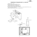
REMOVING OF MAJOR PARTS (LC-32/37P50E)
1. Remove the Terminal Cover1.
2. Remove the 1 lock screw 2 and detach the ID Cover.
3. Remove the 2 lock screws 3 and detach the Hinge Cover.
4. Remove the 4 lock screws 4 and detach the stand.
5. Remove the 21 lock screws 5 and detach the Rear Cabinet.
6. Remove the 7 lock screws 6and detach the Center Angle.
7. Loosen the 2 top cover ass’y fixing screws, and unplug the connecting cable from the KM (P1200) connector of
the AV unit to remove the top cover ass’y.
8. Remove the 3 lock screws 8 from Top Cover, and detach the KEY Unit.
9. Remove the 2 intermediate connector junctions of the speaker boxes to detach the right and left speaker boxes.
9. Remove the 2 intermediate connector junctions of the speaker boxes to detach the right and left speaker boxes.
P1200
KEY Unit
Top Cover Ass’y
Speaker Box-R
Speaker Box-L
Center Angle
6
6
7
8
Rear Cabinet
ID Cover
Terminal Cover
Stand
Hinge Cover
3
5
5
5
4
5
1
2
14
LC-26P50E
LC-32P50E
LC-37P50E
LC-32P50E
LC-37P50E
10.Unplug the FFC/FPC wires from SC4651, SC4652, and SC1202 - SC3701.
11.Unplug the connecting cables from these connectors: CN702, CN1701, CN1702, CN1703, CN1704, CN1705,
11.Unplug the connecting cables from these connectors: CN702, CN1701, CN1702, CN1703, CN1704, CN1705,
P5700, P1201, and P3900.
12.Remove the 9 lock screws 9 and detach the Power Unit.
13.Remove the 5 lock screws 0 and detach the Main Unit.
14.Remove the 5 lock screws q and detach the Main Shield(Top) and Main Shield(Bottom) from Main Unit.
15.Remove the 2 lock screws w and detach the R/C, LED Unit.
16.Remove the 4 lock screws e and 2 lock screws r and detach the AV Unit.
17.Remove the 1 lock screw t and 2 lock screws y and detach the Chassis Frame and Tuneer Shiled from AV
Unit.
SC1202
P5700
P3900
CN1701
CN702
PN7523 PN7517
PN7622 PN7516
CN1703
CN1705
CN1704
SC3701 SC4651
CN1702
SC4652
P1201
Power Unit
R/C LED Unit
Main PWB
Main Shield(Bottom)
Main Shield(Top)
Chassis Frame
AV Unit
Tuner Shield
14
15
16
12
9
13
11
11
11
11
10
11
15
LC-26P50E
LC-32P50E
LC-37P50E
LC-32P50E
LC-37P50E
CN7514
CN7513
CN7512
CN7510
CN7511
CN7509
CN7507
CN7508
CN7508
CN7506
CN7505
CN7514
CN7515
CN7513
CN7512
CN7510
CN7511
CN7509
CN7507
CN7508
CN7508
CN7506
CN7505
Inverter Unit (LC-32P50E)
Inverter Unit (LC-37P50E)
LCD Panel
17
17
18
18
18
18.Loosen the 9 (LC-32P50E) / 10 (LC-37P50E) inverter unit ass’y fixing screws u, and unplug the connecting
cables from the 10 (LC-32P50E) / 11 (LC-37P50E) lamp wire connectors to remove the inverter unit and inverter
shield.
shield.
19.Remove the 3 lock screws i and detach the LCD Unit.
16
LC-26P50E
LC-32P50E
LC-37P50E
LC-32P50E
LC-37P50E
(LC-37P50E)
(LC-32P50E)
20.Remove the 4 LCD Panel Unit Ass’y lock screws o and detach the LCD Panel Unit Assembly.
21.Remove the LCD Panel Unit lock screws (p:8pcs., a:12pcs., s:4pcs. for LC-32P50E, 12pcs. for LC-37P50E).
22.Remove the 2 Glass Fixing Angle lock screws d and detach the Glass Fixing Angle. Remove 4 Source PWB lock
21.Remove the LCD Panel Unit lock screws (p:8pcs., a:12pcs., s:4pcs. for LC-32P50E, 12pcs. for LC-37P50E).
22.Remove the 2 Glass Fixing Angle lock screws d and detach the Glass Fixing Angle. Remove 4 Source PWB lock
clips f. Remove the Back Light Chassis.
20
24
19
21
22
21
20
21
23
Back Light Chassis
Glass Fixing Angle
LCD Panel
Panel Holder
Panel Fixing Angle Ass'y
20
Back Light Chassis
Glass Fixing Holder
LCD Panel
Panel Holder
Panel Fixing Angles Ass'y
20
24
19
21
22
21
20
21
23
22
20
REMOVING OF LCD PANEL UNIT (LC-32P50E/37P50E)
Click on the first or last page to see other LC-26P50E (serv.man7) service manuals if exist.

