Sharp 37GT-27H (serv.man5) Service Manual ▷ View online
9
37GT-27H
3. Vertical Amplifier
3.1. Receive Philips pattern signal.
3.2. Select V-AMPL with channel up or channel down buttons.
3.3. When volume up button is pressed, vertical size of picture decreases.
3.4. When volume down button is pressed, vertical size of picture increases.
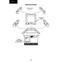
3.5. Adjust the vertical size to obtain picture overscan (Figure 4).
2. Vertical Shift
2.1. Receive Philips pattern signal.
2.2. Select V-SHFT with channel up or channel down buttons.
2.3. When volume up button is pressed, picture moves up.
2.4. When volume down button is pressed, picture moves down.
2.5. Adjust the vertical location to obtain picture centering (Figure 3).
2.1. Receive Philips pattern signal.
2.2. Select V-SHFT with channel up or channel down buttons.
2.3. When volume up button is pressed, picture moves up.
2.4. When volume down button is pressed, picture moves down.
2.5. Adjust the vertical location to obtain picture centering (Figure 3).
1. Horizontal Shift
1.1. Receive Philips pattern signal.
1.2 Select H-SHFT with channel up or channel down buttons.
1.3. When volume up button is pressed, picture moves to the left.
1.4. When volume down button is pressed, picture moves to the right.
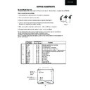
1.5. Adjust the horizontal location to obtain picture centering (Figure 2).
Screen Adjustment
1. Focus Adjustment
1.1. Apply mains voltage of 220V AC/50HZ to TV.
1.2. Receive Philips pattern signal to a level between 60 and 80 dB/
1.1. Apply mains voltage of 220V AC/50HZ to TV.
1.2. Receive Philips pattern signal to a level between 60 and 80 dB/
µ
V.
1.3. Set contrast to 10/10, brightness to 5/10 and colour 0/10.
1.4. Adjust focus potentiometer to obtain maximum definition.
1.4. Adjust focus potentiometer to obtain maximum definition.
2.G2 Adjustment
2.1. Apply mains voltage of 220V AC/50HZ to TV.
2.2. Receive the “Cross Hatch” pattern signal to a level between 60 and 80 dB/
2.1. Apply mains voltage of 220V AC/50HZ to TV.
2.2. Receive the “Cross Hatch” pattern signal to a level between 60 and 80 dB/
µ
V.
2.3. Apply High Voltage Probe to Pin 8 of CRT socket
2.4. Adjust G2 potentiometer until obtaining 525V ±10%.
2.5. Check BKGD. If it is necessary adjust BKGD according to instructions detailed below.
2.4. Adjust G2 potentiometer until obtaining 525V ±10%.
2.5. Check BKGD. If it is necessary adjust BKGD according to instructions detailed below.
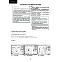
Geometry Adjustment Procedure
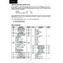
Figure 2
Figure 3
The following adjustments are required when the Picture Tube or IC801 are replaced, or may be nec-
essary after adjustment of the G2 voltage.
essary after adjustment of the G2 voltage.
Colour Adjustment (BKGD) Procedures
1. «GAIN B», «GAIN G»
1.1. Adjust G2.
1.2. Tune a grey scale pattern.
1.3. Adjust colour to minimum.
1.4. Fix R-GAIN value to 32.
1.5. Position colorimeter in the left point of Figure 5.
1.6. Using brightness and contrast buttons, select a luminance of »120 nits.
1.7. Operate again in Service Mode and select location B-GAIN and G-GAIN to obtain colour coordinates:
X = 0.290 ± 0.015
Y = 0.284 ± 0.015
Y = 0.284 ± 0.015
6 5 4 3 2 1 0
Gain point
DC point
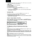
Figure 5
Figure 4
10
37GT-27H
Procedure to Program Functions of Hotel Mode
Below listed can be found the procedure to carry out in the above TV Sets functions called HOTEL MODE as follows:
Consider that HOTEL MODE is implemented by means of HOTEL MODE 1. The HOTEL MODE 2 or HOTEL MODE 3
can be used at the same time than HOTEL MODE 1.
Consider that HOTEL MODE is implemented by means of HOTEL MODE 1. The HOTEL MODE 2 or HOTEL MODE 3
can be used at the same time than HOTEL MODE 1.
HOTEL 1
Blockade of tuning functions
Restriction of sound
HOTEL 2
Blockade of tuning functions
Start on SCART mode + SW when
SCART IS ACTIVE (Front Panel inactive)
HOTEL 3
Blockade of tuning functions
VCR constant changed
Hotel 1 Mode: blockade of the TUNING function by modifying the value in 0A address of the NVM.
-This change besides blocking the tuning function, makes the TV always starts to operate in program 1.
-This change besides blocking the tuning function, makes the TV always starts to operate in program 1.
Procedure:
A) Press the volume up or volume down buttons (RC) as far as the NVM address (green colour) displays “0A” location.
Check the NVM value (red colour) displays the NORMAL VALUE .
Check the NVM value (red colour) displays the NORMAL VALUE .
B) Pay Attention: Press the button 2 (RC) only once. The NORMAL VALUE has been changed to the HOTEL 1 MODE
VALUE now. If the button 2 (RC) is pressed again the NORMAL VALUE is recovered. For the same reason, if a wrong
button has been pressed, NORMAL VALUE can be recovered by pressing the same button again. See NVM table on
page 6.
VALUE now. If the button 2 (RC) is pressed again the NORMAL VALUE is recovered. For the same reason, if a wrong
button has been pressed, NORMAL VALUE can be recovered by pressing the same button again. See NVM table on
page 6.
Restriction of Sound Volume: by modifying the value in 0E address of the NVM.
Notes:
a) Before blocking the tuning function is necessary to memorise the programs according to the necessities of the destina-
tion hotel.
b) Since the Hotel Mode functions have been programmed the end users of the television won’t be able to tune different
channels neither to erase the existent ones.
1.8. Exit Service Mode and check colour coordinates «X» and «Y» at 20 and 120 nits. It may be necessary to repeat the
same procedure or readjust the cuts as show the be below one.
same procedure or readjust the cuts as show the be below one.
2. «CUT R», «CUT G»
2.1. Adjust G2, in the case that it has not been made previously.
2.2. Tune a grey scale pattern.
2.3. Adjust colour to minimum.
2.4. Position colorimeter in the right point of Fig.4.
2.5. Using brightness and contrast buttons, select a luminance of »20 nits.
2.6. Operate again in Service Mode and select location CUT-G and CUT-R to obtain colour coordinates:
X = 0.290 ± 0.015
Y = 0.284 ± 0.015
Y = 0.284 ± 0.015
2.7. Exit Service Mode and check colour coordinates «X» and «Y» at 20 and 120 nits. It may be necessary to repeat
the same procedure or the previous one.
the same procedure or the previous one.
Cancel password (PIN)
The following process describes how to cancel actual password (PIN) when the customer forgets the code.
1. Press channel up or down to select the channel, wich you locked with input PIN number.
2. The TV picture will be blue and the key appear on screen.
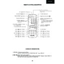
3. Press and hold volume down on the TV and simultaneously press CHILD LOCK button (see Page.43) on the remote
control several times until the key disappears.
2. The TV picture will be blue and the key appear on screen.
3. Press and hold volume down on the TV and simultaneously press CHILD LOCK button (see Page.43) on the remote
control several times until the key disappears.
11
37GT-27H
c) Neither one will be able to get the sound volume in a superior level to the maximum limited in each case.
Procedure:
A) Press the volume up or volume down buttons as far as the NVM address displays 0E location.
Hotel 2 Mode: by modifying the value in 57 address of the NVM .
-When the TV set is switched on by main it starts working in SCART mode.
-When the TV is in STAND-BY mode and it is connected to a VCR through a 21 pins wire, it may be switched on simply
by SLOW SWITCH (VCR in PLAY mode).
-In these circumstances the Front Panel Control Keys does not work.
-When the TV set is switched on by main it starts working in SCART mode.
-When the TV is in STAND-BY mode and it is connected to a VCR through a 21 pins wire, it may be switched on simply
by SLOW SWITCH (VCR in PLAY mode).
-In these circumstances the Front Panel Control Keys does not work.
Procedure:
A) Press the volume up or volume down buttons (RC) as far as the NVM address (green Colour) displays “57” location.
Check the NVM value (red colour) displays the NORMAL VALUE . See NVM Table on page 8.
Check the NVM value (red colour) displays the NORMAL VALUE . See NVM Table on page 8.
B) Pay Attention: Press the button 0 (RC) only once. The NORMAL VALUE has been changed to the HOTEL 2 MODE
VALUE now. If the button 0 (RC) is pressed again the NORMAL VALUE is recovered. For the same reason, if a wrong
button has been pressed, NORMAL VALUE can be recovered by pressing the same button again.
VALUE now. If the button 0 (RC) is pressed again the NORMAL VALUE is recovered. For the same reason, if a wrong
button has been pressed, NORMAL VALUE can be recovered by pressing the same button again.
Hotel 3 Mode: by modifying the value 57 address of the NVM.
-When this it is activated VCR mode is set in all programs.
-When this it is activated VCR mode is set in all programs.
Procedure:
A) Press the volume up or volume down buttons (RC) as far as the NVM address (green colour) displays “57” location.
Check the NVM value (red colour) displays the NORMAL VALUE.
Check the NVM value (red colour) displays the NORMAL VALUE.
B) Pay Attention: Press the button 1 (RC) only once. The NORMAL VALUE has been changed to the HOTEL 3 MODE
VALUE now. If the button 1 (RC) is pressed again the NORMAL VALUE is recovered. For the same reason, if a wrong
button has been pressed, NORMAL VALUE can be recovered by pressing the same button again. See NVM Table on
page 8.
VALUE now. If the button 1 (RC) is pressed again the NORMAL VALUE is recovered. For the same reason, if a wrong
button has been pressed, NORMAL VALUE can be recovered by pressing the same button again. See NVM Table on
page 8.
Check the Hotel Functions work OK.
BUTTON (RC) VALUE SOUND VOL.
TO BE PRESSED STORED LIMITED TO
(4)(3) (EF)(E7) 90%
(5)(4) (DF)(CF) 80%
(6) (BF) 73%
(6)(5) (BF)(9F) 62%
TO BE PRESSED STORED LIMITED TO
(4)(3) (EF)(E7) 90%
(5)(4) (DF)(CF) 80%
(6) (BF) 73%
(6)(5) (BF)(9F) 62%
Display

