Sharp 21KF-80 (serv.man5) Service Manual ▷ View online
10
21KF-80H
Geometry adjustment procedure
To adjust the geometry, follow the procedure outlined below:
1. Tune the set into a Philips test pattern.
2. Enter the service mode as described on page 6.
3. Use the channel up or channel down buttons to enter the desired mode
4. Use the volume buttons to achieve correct setting.
5. When adjustments are complete, use the stand-by button to turn off the set. The adjustment values will be stored
at this point.
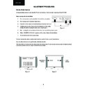
V-LIN
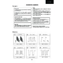
Adjust the vertical linearity control so that the picture centring is as shown in figure 5.
Adjust the vertical linearity control so that the picture centring is as shown in figure 5.
V-AMP
Adjust the vertical amplitude control so that the picture overscans as shown in figure 6.
Adjust the vertical amplitude control so that the picture overscans as shown in figure 6.
V-CENT
Adjust the vertical centring control so that the picture is centred as shown in figure 7.
Adjust the vertical centring control so that the picture is centred as shown in figure 7.
H-CENT
Adjust the horizontal centring control so that the picture is centred as shown in figure 8.
Adjust the horizontal centring control so that the picture is centred as shown in figure 8.
Figure 5
Figure 6
Figure 7
Figure 8
11
21KF-80H
Colour adjustment procedure
The following adjustments should only be carried out when the CRT or IC801 are replaced.
Notes:
1. This adjustment must be done after warming up the unit for 30 minutes or longer with a beam current over 700 µA.
2. The red value «DRI-RS» should be fixed to 42. (Refer to “How to access service mode” section).
3. «DRI-GS» adjustment alters “Y” coordinate.
4. «DRI-BS» adjustment alters “X” and “Y” coordinates.
Adjustment method 1 (using the signal generator, varying the picture signal)
1. Adjust G2.
2. Input a white pattern with burst signal from SCART.
3. Position the colorimeter in the centre of screen.
4. Adjusting input signal level, select a luminance of 70 nits.
5. Operate again in “service mode“ and select «DRI-GS» and/or «DRI-BS» locations to obtain colour coordinates:
2. Input a white pattern with burst signal from SCART.
3. Position the colorimeter in the centre of screen.
4. Adjusting input signal level, select a luminance of 70 nits.
5. Operate again in “service mode“ and select «DRI-GS» and/or «DRI-BS» locations to obtain colour coordinates:
6. Reset the TV with the mains switch button to store the adjustment and exit service mode.
7. Check colour coordinates “X” and “Y” at 20 a 120 Nits. It may be necessary to repeat the same procedure to
obtain the above values.
7. Check colour coordinates “X” and “Y” at 20 a 120 Nits. It may be necessary to repeat the same procedure to
obtain the above values.
Adjustment method 2 (using the signal generator, with a fixed picture signal)
1. Adjust G2.
2. Tune a white pattern with burst signal.
3. Operate in “service mode”:
4. Using «SUB-CON», select a luminance of 70 nits.
5. Operate again in “service mode“ and select «DRI-GS» and/or «DRI-BS» locations to obtain colour coordinates:
2. Tune a white pattern with burst signal.
3. Operate in “service mode”:
4. Using «SUB-CON», select a luminance of 70 nits.
5. Operate again in “service mode“ and select «DRI-GS» and/or «DRI-BS» locations to obtain colour coordinates:
6. Select «SUB-CON». Return data to “63”.
7. Reset the TV with the mains switch button to store the adjustment and exit service mode.
8. Check colour coordinates “X” and “Y” at 20 a 120 Nits. It may be necessary to repeat the same procedure to
obtain the above values.
7. Reset the TV with the mains switch button to store the adjustment and exit service mode.
8. Check colour coordinates “X” and “Y” at 20 a 120 Nits. It may be necessary to repeat the same procedure to
obtain the above values.
X=0.290 ± 0.015 Y=0.284 ± 0.015 Screen Temperature: 8900º K-20 MPCD
X=0.290 ± 0.015 Y=0.284 ± 0.015 Screen Temperature: 8900º K-20 MPCD
Display

