Sharp XV-Z201E (serv.man5) Service Manual ▷ View online
9
XV-Z200U/E, XV-Z201E
DT-300
DT-300
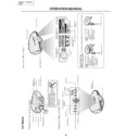
Part Names
Rem
ote
Co
ntr
o
l
(Fr
ont
V
iew)
Rem
ote
Co
ntr
o
l
(T
o
p
V
iew
)
FREEZE button
ST
ANDBY button
ENTER button
KEYSTONE button
UNDO button
INPUT 1 button
INPUT 2 button
INPUT 4 button
AUTO SYNC button
RESIZE button
PICTURE SETTING button
MENU button
ON button
ADJUSTMENT buttons
()
INPUT 3 button
DIGIT
AL INPUT button
RGB/COMP
. button
Remote contr
ol signal transmitters
"
/'
/\
/|
Operating the Remote Control
■
Th
e re
mo
te
co
nt
ro
l
ca
n
be
us
ed
to
co
nt
ro
l
th
e
pr
oj
ec
to
r
wi
th
in
t
h
e
r
a
n
g
e
s
sh
o
w
n
in
t
h
e
i
ll
u
s
tr
a
ti
o
n.
Note
•
Th
e si
gn
al
fr
om
th
e re
mo
te
co
nt
ro
l
ca
n be
re
fl
ec
te
d of
f a sc
re
en
for ea
sy
op
er
ati
on
.
Ho
w
e
v
e
r,
th
e ef
fe
c
ti
v
e di
st
an
ce
of
th
e
si
gn
al
ma
y di
ff
er
d
u
e
t
o
th
e
sc
re
en
m
a
te
ri
a
l.
Whe
n u
sin
g t
he
rem
ote
co
ntr
ol:
•
Be
su
re
no
t
to
dr
op
,
or
e
x
po
se
to
mo
is
tu
re
or
hi
gh
te
mp
er
at
ur
e
.
•
Th
e re
mo
te
co
nt
ro
l ma
y ma
lf
un
ct
io
n un
de
r a fl
uo
re
sc
en
t la
mp
.
Unde
r that
circ
umst
ance
, mo
v
e
the
proj
ecto
r a
w
a
y
from
the
fluo
-
re
sc
en
t la
mp
.
Incorrect use of the batteries ma
y cause them to leak or e
xplode
. Please f
ollo
w the precautions belo
w
.
Caution
•
Inser
t the batter
ies making sure the polar
ities correctly match the
and
mar
ks inside the batter
y compar
t-
ment.
•
Batter
ies of diff
erent types ha
v
e
diff
erent proper
ties
, theref
ore do not
mix batter
ies of diff
erent types
.
•
Do not mix ne
w and old batter
ies
.
This ma
y shor
ten the lif
e of ne
w batter
ies or ma
y cause old batter
ies to leak.
•
Remo
v
e
the
batter
ies from
the remote
control once
the
y
ha
v
e
r
un out,
as lea
v
ing them can
cause them
to leak.
Batter
y
fluid from leak
ed
batter
ies is har
mful to
y
our skin, theref
ore be
sure to first wipe
them and then remo
v
e
them using a cloth.
•
The batter
ies included with this projector ma
y e
xhaust o
v
er a shor
t per
iod, depending on ho
w the
y
are k
ept.
Be sure to replace them as soon as possib
le with ne
w batter
ies when the
y
ha
v
e
r
un out.
•
Remo
v
e
the batter
ies from the remote control if y
ou will not be using the remote control f
o
r a long time
.
A
v
a
ila
ble
Ra
nge
of
th
e R
emo
te
Con
tr
o
l
45
˚
23' (7 m)
30
˚
30
˚
45
˚
30
˚
Ins
e
r
ting
th
e B
a
tt
eri
e
s
Th
e ba
tt
er
ie
s (t
w
o
“
A
A”
si
z
e
) ar
e
i
n
c
lud
ed
i
n
th
e pa
c
k
a
g
e
.
1
Pull
do
wn
the
tab
on
the
co
ve
r
and remo
ve the co
ve
r
to
wa
rd
the
dire
ctio
n of
the
arr
o
w
.
2
Inse
rt
the inc
lude
d batter
ies.
•
In
se
rt
th
e ba
tt
er
ie
s ma
ki
ng
su
re
th
e
po
la
ri
ti
e
s
cor
re
ct
ly
ma
tc
h the
an
d
ma
rk
s
in
si
de
th
e
ba
tt
er
y
co
mp
ar
t-
me
nt
.
3
Inser
t the lo
wer tab of the
co
v
er into the opening,
and
lo
wer the
co
ver
unti
l
it
c
lic
ks
in p
lace
.
Remote contr
o
l
Remote contr
ol
10
XV-Z200U/E, XV-Z201E
DT-300
DT-300
Connecting Pin Assignments
RS-232C P
o
rt
:
9-pin D-sub male connector
Pin No.
Signal
Name
I/O
Ref
erence
1
Not connected
2
R
D
Receive Data
Input
Connected to inter
nal cir
cuit
3
S
D
Send Data
Output
Connected to inter
nal cir
cuit
4
Reserved
Connected to inter
nal cir
cuit
5
S
G
Signal Gr
ound
Connected to inter
nal cir
cuit
6
Reserved
Connected to inter
nal cir
cuit
7
Reserved
Connected to inter
nal cir
cuit
8
Reserved
Connected to inter
nal cir
cuit
9
Not connected
D
VI-I (INPUT 2 / DIGIT
AL INPUT) por
t :
29 pin connector
•
D
VI
Dig
ita
l I
NPU
T
Pi
n No
.
S
ig
n
a
l
P
in
No
.
S
ig
n
a
l
1
T.M
.D
.S
d
a
ta
2
–
16
Ho
t pl
ug
d
e
tec
ti
on
2
T.M
.D
.S
d
a
ta
2+
17
T.
M
.D
.S
d
a
ta
0
–
3
T.M
.D
.S
d
a
ta
2 sh
ie
ld
18
T.
M
.D
.S
d
a
ta
0+
4
N
o
t co
nn
ec
te
d
1
9
T.M
.D
.S
d
a
ta
0 sh
ie
ld
5
N
o
t co
nn
ec
te
d
2
0
N
o
t co
nn
ec
te
d
6
D
D
C
cl
oc
k
2
1
N
o
t co
nn
ec
te
d
7
D
DC
d
a
ta
2
2
T.
M.
D.
S cl
oc
k sh
ie
ld
8
N
o
t co
nn
ec
te
d
2
3
T.M
.D
.S
c
lo
c
k
+
9
T.M
.D
.S
d
a
ta
1
–
2
4
T.
M.
D.
S cl
oc
k
–
10
T.
M
.D
.S
d
a
ta
1+
C1
No
t co
nn
ec
te
d
11
T.
M
.D
.S
d
a
ta
1 sh
ie
ld
C2
No
t co
nn
ec
te
d
12
No
t co
nn
ec
te
d
C
3
N
o
t co
nn
ec
te
d
13
No
t co
nn
ec
te
d
C
4
N
o
t co
nn
ec
te
d
14
+5
V po
we
r
C
5
G
ro
u
n
d
15
Gr
ou
nd
•
D
VI
Ana
log
RG
B I
npu
t
Pi
n No
.
S
ig
n
a
l
P
in
No
.
S
ig
n
a
l
1
N
o
t co
nn
ec
te
d
1
6
H
o
t pl
ug
d
e
te
c
ti
o
n
2
N
o
t co
nn
ec
te
d
1
7
N
o
t co
nn
ec
te
d
3
N
o
t co
nn
ec
te
d
1
8
N
o
t co
nn
ec
te
d
4
N
o
t co
nn
ec
te
d
1
9
N
o
t co
nn
ec
te
d
5
N
o
t co
nn
ec
te
d
2
0
N
o
t co
nn
ec
te
d
6
D
D
C
cl
oc
k
2
1
N
o
t co
nn
ec
te
d
7
D
D
C
da
ta
22
No
t co
nn
ec
te
d
8
V
er
ti
ca
l sy
nc
23
No
t co
nn
ec
te
d
9
N
o
t co
nn
ec
te
d
2
4
N
o
t co
nn
ec
te
d
10
No
t
co
nn
ec
te
d
C
1
A
n
a
lo
g
i
n
p
u
t R
e
d
11
No
t
co
nn
ec
te
d
C
2
A
n
a
lo
g
i
n
p
u
t G
reen
12
No
t
co
nn
ec
te
d
C
3
A
n
a
lo
g
i
n
p
u
t B
lu
e
13
No
t co
nn
ec
te
d
C
4
H
o
ri
z
o
n
ta
l
s
y
n
c
14
+5
V po
we
r
C
5
G
ro
u
n
d
15
Gr
ou
nd
•
D
VI
Ana
log
Co
mpo
nen
t I
npu
t
Pi
n No
.
S
ig
n
a
l
P
in
No
.
S
ig
n
a
l
1
N
o
t co
nn
ec
te
d
1
6
N
o
t co
nn
ec
te
d
2
N
o
t co
nn
ec
te
d
1
7
N
o
t co
nn
ec
te
d
3
N
o
t co
nn
ec
te
d
1
8
N
o
t co
nn
ec
te
d
4
N
o
t co
nn
ec
te
d
1
9
N
o
t co
nn
ec
te
d
5
N
o
t co
nn
ec
te
d
2
0
N
o
t co
nn
ec
te
d
6
N
o
t co
nn
ec
te
d
2
1
N
o
t co
nn
ec
te
d
7
N
o
t co
nn
ec
te
d
2
2
N
o
t co
nn
ec
te
d
8
N
o
t co
nn
ec
te
d
2
3
N
o
t co
nn
ec
te
d
9
N
o
t co
nn
ec
te
d
2
4
N
o
t co
nn
ec
te
d
10
No
t
co
nn
ec
te
d
C
1
A
n
a
lo
g
i
n
p
u
t P
r/
C
r
11
No
t
co
nn
ec
te
d
C
2
A
n
a
lo
g
i
n
p
u
t Y
12
No
t
co
nn
ec
te
d
C
3
A
n
a
lo
g
i
n
p
u
t P
b
/C
b
13
No
t co
nn
ec
te
d
C
4
N
o
t co
nn
ec
te
d
14
No
t co
nn
ec
te
d
C
5
G
ro
u
n
d
15
Gr
ou
nd
17
•••
••••••
~
•••
••••••
••••
~
••••
••••
~
••••
24
18
23
C3
2
1
1
9
16
C1
C2
C4
C5
8
7
7
6
7
8
9
1
2
3
4
5
PC con
tr
ol
A
com
pu
te
r
can
be
us
ed
to
co
nt
ro
l th
e
pr
oje
c
to
r b
y
con
ne
ct
in
g an RS-
23
2C
ca
b
le (n
ul
l mod
em
, cr
oss
ty
pe
,
co
mm
er
ci
al
ly
a
v
ai
la
b
le
)
to
th
e
pr
oj
ec
to
r.
Com
m
un
ica
tio
n co
ndi
tio
ns
Se
t
th
e
se
ri
al
p
o
rt
se
tt
in
gs
o
f
th
e
co
mp
ut
er
t
o
ma
tc
h
th
at
o
f
th
e
ta
b
le
.
Si
gn
al
f
orm
at
: Co
nf
orm
s t
o
R
S
-2
3
2
C
st
an
da
rd
.
Ba
ud
ra
te
: 9
,6
0
0
bp
s
Da
ta
len
g
th
: 8 bi
ts
P
a
ri
ty
bi
t:
N
o
n
e
St
op
bit
: 1 b
it
F
lo
w
c
o
nt
ro
l:
No
ne
Bas
ic for
mat
Co
mm
an
ds
fr
om
th
e com
pu
te
r are
se
nt
in
th
e f
o
ll
o
w
in
g or
der
:
co
mm
an
d,
pa
ra
me
te
r,
an
d ret
ur
n cod
e
.
Af
te
r
th
e
pr
oje
c
to
r p
roce
ss
es
t
h
e
c
o
m
m
a
n
d
f
rom
t
h
e
c
o
m
p
u
te
r,
i
t
se
nd
s
a
re
sp
on
se
c
o
d
e
to
t
h
e
c
o
m
p
u
te
r.
Inf
o
•
Wh
en
mo
re
th
an
on
e
co
de
is
be
in
g
se
nt
,
se
nd
ea
ch
co
mm
an
d
on
ly
af
te
r
th
e
OK
re
sp
on
se
co
de
f
o
r th
e
pr
e
v
io
u
s
co
mm
an
d
fr
om
t
h
e
p
ro
je
c
to
r i
s
v
e
ri
fi
e
d
.
Note
•
Wh
en
us
in
g
th
e
co
mp
ut
er
co
nt
ro
l fu
nc
ti
on
of
th
e
pr
oj
ec
to
r,
th
e
pr
oj
ec
to
r’
s
op
er
at
in
g
st
at
us
ca
nn
ot
be
re
ad
b
y
th
e co
mp
ut
er
.
Th
er
ef
or
e
,
co
nf
ir
m th
e st
at
us
b
y
tr
an
sm
it
ti
ng
th
e di
sp
la
y co
mm
an
ds
f
o
r
ea
ch
ad
ju
st
me
nt
me
n
u
an
d ch
ec
kin
g th
e st
at
us
w
it
h
th
e on
-s
cr
ee
n di
sp
la
y.
Com
m
an
ds
Exa
mpl
e:
•
Wh
en
po
w
e
r on
.
Response code for
mat
Nor
mal r
esponse
Pr
oble
m
r
espo
nse
(com
muni
cati
on er
ro
r or
inco
rr
ect comm
and)
Command for
mat
(RS-232C) Specifications and Command Settings
→ ←
PO
W
R
_
1
__
OK
Pr
ojector
Computer
Retur
n code (
0DH
)
C1 C2 C3 C4 P1 P2 P3 P4
Command 4-digit
Parameter 4-digit
O K
Retur
n code (
0DH
)
E R R
Retur
n code (
0DH
)
Note
•
If
a
n
un
de
rb
ar
(
_
)
ap
pe
ar
s
in
t
h
e
p
a
ra
me
te
r
co
lu
mn
,
en
te
r
a
sp
ac
e
.
CONTROL CONTENTS
POWER ON
ST
ANDBY
INPUT 1 (COMPONENT 1)
INPUT 2 (COMPONENT 2)
INPUT 3 (S-VIDEO)
INPUT 4 (VIDEO)
DIGIT
AL INPUT MODE
OK OR ERR
OK OR ERR
OK OR ERR
OK OR ERR
OK OR ERR
OK OR ERR
OK OR ERR
P
P
I
I
I
I
I
O
O
V
V
V
V
V
W
W
E
E
E
E
E
R
R
D
D
D
D
D
_
_
_
_
_
_
_
_
_
_
_
_
_
_
_
_
_
_
_
_
_
1
0
1
2
3
4
5
BUTTONS & REMOTE CONTROL BUTTONS
COMMAND
PA
RAMETER
RETURN
11
XV-Z200U/E, XV-Z201E
DT-300
DT-300
Menu Bar Items
Language ( )
English
Deutsch
Espa
ñ
ol
Nederlands
Fran
ç
ais
Italiano
Svenska
Por
tugu
ê
s
Fr
ont
Ceiling
Fr
ont
Rear
Ceiling
R
ear
Pictur
e ( )
Tint
30
30
Color
30
30
Sharp
30
30
Contrast
30
30
Bright
30
30
Red
30
30
Blue
30
30
Reset
5500K
6500K
8500K
9300K
10500K
Standar
d
Cinema 1
Cinema 2
Memor
y
2
Memor
y
3
Memor
y
4
Memor
y
5
Memor
y
OFF
Cinema 3
7500K
CLR T
emp
Gamma
White Emphasis [ON/OFF]
Pictur
e Setting
Memor
y
1
Fine Sync ( )
Auto Sync [ON/OFF]
Clock
30
30
30
30
30
30
Phase
15
15
H-Pos
V
-Pos
Reset
Special Modes
Signal Info
Resolution
Hor Fr
eq
V
e
rt
Fr
eq
640
480
37.5 kHz
72 Hz
640
480
720
480
480P
RGB
Backgr
ound [None/Blue]
Options ( )
Component
Auto Power Of
f
[ON/OFF]
Menu Position
Menu Color [Opaque/T
ranslucent]
Center
Lamp Timer (Life)
OSD Display [ON/OFF]
Signal T
ype
Upper Right
Lower Right
Upper Left
Lower Left
Eco Mode [Eco/Standar
d]
PRJ Mode ( )
10
0
10
0
10
0
10
0
10
0
10
0
■
INPUT 1 / 2 / DIGIT
AL INPUT Mode
Main men
u
Sub men
u
Main men
u
Note
•
The r
esolution, ver
tical fr
equency and horizontal
fr
equency figur
es displayed above ar
e for
example purposes only
.
•“
Color
”,
“Tint
”, and
“Sharp
” do not appear when
“RGB
” is selected in INPUT 2 mode.
•“
Signal T
ype
” is not displayed when using
INPUT 1.
•“
Color
”,
“Tint
”,
“Sharp
”,
“Clock
”,
“Phase
”,
“H-
Pos
”,
“V
-Pos
”,
“Special Modes
” and
“Auto Sync
”
cannot be used in the DIGIT
AL INPUT mode.
•“
Clock
”,
“Phase
” and
“Auto Sync
” cannot be
used in the Component mode.
Lamp Timer (Life)
Picture ( )
Tint
Color
Sharp
Contrast
+30
-30
+30
-30
+30
-30
+30
-30
+30
-30
+30
-30
+30
-30
Bright
Red
Blue
Reset
5500K
3D Progressive6500K
3D Progressive
3D Progressive8500K
3D Progressive9300K
3D Progressive10500K
3D ProgressiveStandard
3D ProgressiveCinema 1
3D ProgressiveCinema 2
3D ProgressiveMemory 2
3D ProgressiveMemory 3
3D ProgressiveMemory 4
3D ProgressiveMemory 5
Auto
3D ProgrOFFessiveMemory OFF
3D ProgressiveCinema 3
Background [None/Blue]
Options ( )
PAL
NTSC3.58
NTSC4.43
PAL
–
M
PAL
–
60
SECAM
Language ( )
English
Deutsch
Espa
ñ
ol
Nederlands
Fran
ç
ais
Italiano
Svenska
Portugu
ê
s
Auto Power Off
[ON/OFF]
Menu Position
Menu Color [Opaque/Translucent]
Center
PRJ Mode ( )
Front
Ceiling
F
ront
Rear
Ceiling
Rear
7500K
CLR Temp
Gamma
White Emphasis [ON/OFF]
Picture Setting
3D ProgressiveMemory 1
OSD Display [ON/OFF]
Video System
PAL
–
N
Upper Right
Lower Right
Upper Left
Lower Left
Eco Mode
[Eco/Standard]
10
0
10
0
10
0
10
0
10
0
10
0
Note
•“
T
int
” cannot be used with P
AL, SECAM, P
AL-M,
P
AL-N or P
AL-60.
INPUT 3 / 4 Mode
Main men
u
Sub men
u
Main men
u
■
Display

