Sharp XV-Z201E (serv.man7) Service Manual ▷ View online
13
XV-Z200U/E, XV-Z201E
DT-300
DT-300
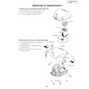
REMOVING OF MAJOR PARTS
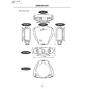
1. Removing the swivel stand and the lamp box.
1-1. Remove lock lever, and remove the swivel stand.
1-2. Loosen 1 scrwew, and remove the lamp door.
1-3. Loosen 3 screws, and take out a lamp box.
2-1. Push front end of the side cover from bottom,
and remove a hook.
2-2. Pull the side cover in the direction of the ar-
row, and remove it.
2-3. Remove 8 screws and 1connector, and re-
move a top body.
2. Removing the side covers and the top body.
1-1
1-2
Lamp Box
Lamp door
Swivel Stand
2-1
2-1
2-3
2-3
2-3
2-2
2-3
2-3
2-2
Side Cover (L)
Side Cover (R)
Top Body
(KY)
(KY)
14
XV-Z200U/E, XV-Z201E
DT-300
DT-300
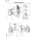
3. Removing the main PWB.
3-1. Remove 6 screws.
3-2. Remove each connector on the main PWB.
4. Removing the power unit.
4-1. Remove each connector on the power PWB.
4-2. Remove 2 screws, and remove the power unit fan.
4-3. Remove 3 screws, and take out the power unit as-
sembly.
4-4. Remove 6 screws, and remove power shield.
3-2
3-2
3-1
3-2
3-2
Main PWB
(TF)
(DA)
(TD)
(BA)
(FD)
(FB)
(PG)
(FA)
(FC)
(ED)
(TC)
(TH)
(RB)
4-1
4-2
4-3
4-4
4-4
4-3
Power PWB
Power Unit Fan
Power Shield
(EC)
(EA)
(EA1)
(EB)
15
XV-Z200U/E, XV-Z201E
DT-300
DT-300
6. Removing the optic mechanism unit.
6-1. Remove 5 screws, and remove the optic mechanism
unit.
5. Removing the Ballast unit.
5-1. Remove lens shift knob.
5-2. Remove 2 screws, and remove the ballast socket.
5-3. Remove 3 screws, and remove the ballast unit.
5-4. Remove shielding plate, and remove 2 connectors
on the ballast PWB.
5-5. Remove 2 screws, and remove ballast PWB.
5-3
5-2
5-4
5-1
5-5
Shielding Plate
Ballast PWB
Lens Shift Knob
Exhaust Duct Unit
(EC)
(BA)
6-1
Optic Mechanism Unit
16
XV-Z200U/E, XV-Z201E
DT-300
DT-300
8. Removing the formatter PWB.
8-1. Remove 2 screws, and remove the angle.
8-2. Remove 5 screws, and remove the blower fan unit.
8-3. Remove 2 screws, and remove the heat sink.
8-4. Remove 4 screws. Remove the backer plate M, stud
plate M, stud spring M, and 2 connectors from the
formatter PWB. After that, remove the formatter PWB.
7. Removing the each other PWBs.
7-1. Remove 1 screw, and remove front R/C receiver PWB
unit .
7-2. Remove 1 screw, and remove LED PWB unit.
7-3. Remove 1 screw, and remove a terminal-2 PWB unit.
7-4. Remove 2 screws, and remove an AC socket.
7-5. Remove 1 screw, and remove rear R/C receiver PWB
unit.
7-6. Remove 1 screw, and remove terminal-1 PWB unit.
7-2
7-1
7-3
7-4
7-5
7-6
AC Socket
Terminal-2 PWB
Front R/C Receiver PWB
Rear R/C Receiver PWB
LED PWB
Terminal-1 PWB
8-1
8-2
8-2
8-4
8-3
Blower Fan Unit
Angle
Lamp Shield
Heat Sink
Stud Spring M
Stud M
Backer Plate M
Formatter PWB
DMD
Display

