Sharp PG-M20S (serv.man11) Service Manual ▷ View online
32
PG-M20S
PG-M20X
PG-M20X
No
Yes
Does POWER LED flicker in red
(for 2 seconds)?
(for 2 seconds)?
No
Is there B+3.3V output at pins (12)
and (13) of CN3701?
and (13) of CN3701?
Is there 6V output at pins (5) and
(6) of P2003?
(6) of P2003?
Yes
Go to "Checking of PC I/F Unit", and check
the flexible connector.
Communication error of sub-microprocessor
(KEY) and SH microprocessor (PC I/F unit)
Pins (20) and (21) of P2001.
the flexible connector.
Communication error of sub-microprocessor
(KEY) and SH microprocessor (PC I/F unit)
Pins (20) and (21) of P2001.
Yes
Go to "Checking of Power Unit"
Check Q2001 thru Q2004
and IC2001.
and IC2001.
No
No
Yes
Is Bu+6.2V signal outputted?"
Go to "Checking of
Power Unit"
Power Unit"
Yes
No
Is Bu+3.3V signal outputted?
Check IC2010 and its
periphery.
periphery.
Check IC2010 and its
periphery.
periphery.
Yes
No
Is 3.3V signal output at pin
(19) of IC2001?
(19) of IC2001?
Check IC2001 and its
periphery and go to
"Checking of Remote Control
Communication".
periphery and go to
"Checking of Remote Control
Communication".
Checking of Sub-microprocessor
and Its Periphery
and Its Periphery
33
PG-M20S
PG-M20X
PG-M20X
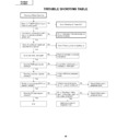
Checking of Low-pass Filter Circuit
Yes
Is video signal is inputted to pins
(4), (8) and (12) of IC3851?
(4), (8) and (12) of IC3851?
Is video signal inputted to pins
(24), (21) and (17) of IC3851?
(24), (21) and (17) of IC3851?
Is the video signal inputted to pins
(8), (17) and (23) of IC8013
(AD9888) of the PC I/F unit?
(8), (17) and (23) of IC8013
(AD9888) of the PC I/F unit?
No
IC3851 is defective.
If the picture quality is abnormal, check whether
or not the following voltages are outputted to
pin (28) of IC3851.
0.3 V for 480i, 1 V for 720p, 1080i, Check IC301.
If the picture quality is abnormal, check whether
or not the following voltages are outputted to
pin (28) of IC3851.
0.3 V for 480i, 1 V for 720p, 1080i, Check IC301.
Yes
Check Q3851, Q3852 and Q3853
and their periphery.
and their periphery.
No
Is video signal is inputted to pins
(16), (20) and (24) of IC3001?
(16), (20) and (24) of IC3001?
Yes
No
The low-pass filter circuit on the
input PWB is normal. Does the
picture appear?
input PWB is normal. Does the
picture appear?
Yes
No
Check pins (4), (8) and (12) of
SC3001.
SC3001.
Normal
Abnormal
Check Q3854 and
Q3855.
Q3855.
Check the PC I/F unit.
Check DVI (analog)
input.
Check DVI (analog)
input.
Yes
No
Check the SOG
circuit or IC8013
and its periphery.
circuit or IC8013
and its periphery.
Check IC8013
and its periphery.
and its periphery.
End
34
PG-M20S
PG-M20X
PG-M20X
Feed the 480i component signal in INPUT 1.
Select INPUT 1 using the set's key or the remote controller.
Select 480i among the special modes on the user
menu screen.
Select INPUT 1 using the set's key or the remote controller.
Select 480i among the special modes on the user
menu screen.
Is 480i selected among the special
modes?
modes?
Does the contour of picture
appear clear.
appear clear.
Confirmation of synchronization.
Is Y signal including sync signal
inputted to pin (3) of IC3502?
Is Y signal including sync signal
inputted to pin (3) of IC3502?
Is picture outputted?
Is the color normal?
No
Is the signal type set to the
component?
component?
In case of monitor output,
disconnect the monitor output
cable.
disconnect the monitor output
cable.
Set the monitor output.
Check the monitor output
equipment and cable.
Check the monitor output
equipment and cable.
No
Yes
Yes
No
Yes
Yes
No
Yes
Abnormal
No
Set the signal type.
IC8025 is defective.
Select 480i.
Restored to normal condition
Yes
End
Checking of DTV
(480i Component Input)
(480i Component Input)
Check IC8016
(Video decoder).
(Video decoder).
Go to "Checking of
Low-pass Filter Circuit"
Low-pass Filter Circuit"
Check IC3501 and its
periphery.
periphery.
Yes
No
35
PG-M20S
PG-M20X
PG-M20X
Feed the composite video signal to
INPUT 3. Select INPUT 3 using the
set's key or the remote controller.
INPUT 3. Select INPUT 3 using the
set's key or the remote controller.
Feed the S-video signal to INPUT 2.
Select INPUT 2 using the set's key
or the remote controller. Does the
picture appear?
Select INPUT 2 using the set's key
or the remote controller. Does the
picture appear?
Does the picture appear?
Check IC3501 and its peripheral
circuit.
circuit.
Is the picture disturbed?
Is the video signal including sync
signal inputted to pin (3) of SC3001
on the input PWB?
signal inputted to pin (3) of SC3001
on the input PWB?
Yes
Yes
No
No
No
No
Check IC8016 (video decoder)
of PC board and its periphery.
Check Q8002.
of PC board and its periphery.
Check Q8002.
Yes
Is the video signal including sync
signal inputted to pin (7) of IC3501
on the input PWB?
signal inputted to pin (7) of IC3501
on the input PWB?
No
Check Q3512 and Q3513 on
the input PWB.
the input PWB.
Yes
Is the color normal?
End
Yes
No
Yes
Yes
No
Checking of Video Input
Check IC8363 and
IC8025 (CVIC2) and
their periphery.
IC8025 (CVIC2) and
their periphery.
Check Q3502 on the
input PWB.
input PWB.
Is the C signal inputted
to pin (11) of SC3001?
to pin (11) of SC3001?
1
1
Yes
No
Are pin(5) (horizontal) and
pin(10) (vertical) signals
inputted to IC8363 on the
PC I/F unit?
pin(10) (vertical) signals
inputted to IC8363 on the
PC I/F unit?
Click on the first or last page to see other PG-M20S (serv.man11) service manuals if exist.

