Sharp MX-M950 / MX-MM1100 (serv.man21) Service Manual ▷ View online
MX-M1100 PHOTOCONDUCTOR SECTION i – 9
8)
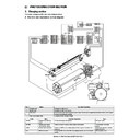
Hold the handle (a), and pull out the process unit (b) until it
stops.
stops.
9)
Hold the green label section (a) on the process unit frame, and
lift it up to remove completely.
lift it up to remove completely.
a. Process control sensor / Discharge lamp
1)
Remove the process unit.
2)
Remove the OPC drum unit.
3)
Disconnect the connector (a), and remove the screw (b).
Remove the process control sensor (c).
Remove the process control sensor (c).
4)
Remove the blue screw (a), and remove the cover (b).
5)
Disconnect the connector (a), extend the pawl (c), and remove
the discharge lamp (b).
* Be careful not to break the pawl. (c).
the discharge lamp (b).
* Be careful not to break the pawl. (c).
b. Temperature humidity sensor 1 / Surface potential sensor /
PTDL PWB
1)
Remove the process unit.
2)
Remove the OPC drum unit.
3)
Remove the screw (a), and remove the cover (b).
a
b
a
a
a
b
c
a
b
a
b
c
b
a
a
b
MX-M1100 PHOTOCONDUCTOR SECTION i – 10
4)
Disconnect the connector (a), and remove the temperature
humidity sensor 1 (b).
humidity sensor 1 (b).
5)
Disconnect the connector (a), and remove the snap band (b).
6)
Remove the screw (a) and the E-ring (b). Remove the shaft
(c). Remove the holder (d) from the surface potential sensor
(e).
(c). Remove the holder (d) from the surface potential sensor
(e).
7)
Disconnect the connector (a), and remove the PTDL PWB (b).
* When replacing the PTDL PWB, replace it together with the
* When replacing the PTDL PWB, replace it together with the
surface potential sensor.
c. DL PWB
1)
Remove the process unit.
2)
Remove the OPC drum unit.
3)
Disconnect the connector (a), and remove the step screw (b).
Remove the frame (c).
Remove the frame (c).
4)
Remove the screw (a), and remove the plate (b).
a
b
a
b
b
a
b
c
d
d
e
a
b
b
c
a
a
a
b
MX-M1100 PHOTOCONDUCTOR SECTION i – 11
5)
Remove the holder (a), and remove the DL PWB (b). Discon-
nect the connector (c).
nect the connector (c).
d. Separation solenoid
1)
Remove the process unit.
2)
Remove the OPC drum unit.
3)
Remove the screw (a), and remove the plate (b).
4)
Disconnect the connector (a), and remove the frame (b).
5)
Disconnect the connector (a), and remove the screw (b).
Remove the separation solenoid unit (c).
Remove the separation solenoid unit (c).
6)
Disconnect the connector (a), and remove the screw (b).
Remove the separation solenoid (c).
Remove the separation solenoid (c).
B. Main charger unit
a
c
b
a
a
b
b
a
b
b
a
b
Unit
Parts
Page
Main charger
Unit
Unit
A
MC cleaner home position detection
i - 13/a
B
Main charger cleaning motor
i - 13/b
a
b
b
c
a
a
b
b
c
B
A
MX-M1100 PHOTOCONDUCTOR SECTION i – 12
(1) Main charger unit
1)
Open the front cover (a), and pull out the toner tray (b) slightly.
2)
Remove the screw (a), and remove the cover (b).
3)
Remove the blue screw (a), and remove the plate (b).
4)
Slide the developing unit (a) to the right, and pull it out until it
stops.
stops.
5)
Hold the handle (a) of the developing unit, and lift it up to
remove completely.
* When placing the developing unit on a floor, use the stand
remove completely.
* When placing the developing unit on a floor, use the stand
(b) and put the unit on it.
6)
Disconnect the connector (a), and remove the blue screw (b).
Pull out the main charger unit (c).
Pull out the main charger unit (c).
a
b
a
a
b
a
a
a
b
a
b
a
b
c
a
Click on the first or last page to see other MX-M950 / MX-MM1100 (serv.man21) service manuals if exist.

