Sharp MX-M950 / MX-MM1100 (serv.man21) Service Manual ▷ View online
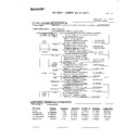
MX-M1100 PHOTOCONDUCTOR SECTION i – 1
[i] PHOTOCONDUCTOR SECTION
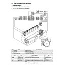
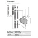
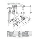
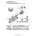
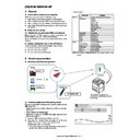
1. Charging section
This section charges the OPC drum with a negative charge.
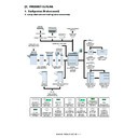
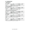
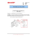
A. Electrical and mechanism relation diagram
No.
Name
Function / Operation
1
Charger wire
Charges the OPC drum.
2
Screen grid
Charges the OPC drum evenly.
3
OPC drum
Forms electrostatic latent images by laser beams. Forms toner images from the electrostatic latent images
through the developing process.
through the developing process.
4
Main high voltage PWB
Outputs the main charger voltage.
Code
Name
Function / Operation
Type
MCCM
Charger wire cleaning
motor
motor
Drives the charger wire cleaner.
DC brush motor
MCHPS
Charger wire cleaner
home position sensor
home position sensor
Detects the home position of the charger wire cleaner.
Transmission type photo
sensor
sensor
DESS
Surface potential sensor
Detects the OPC drum surface potential after exposure and after non-
exposure.
exposure.
Feed-back type drum surface
potential sensor
potential sensor
DM
OPC drum motor
Drives the OPC drum, the OPC drum cleaner section, and the transfer
section.
section.
DC brushless motor
MCHPS1
MCHPS1
MCCM
MCCM
1
2
3
3
1
2
4
DM
DM
DESS
DESS
DESS
DESS
DSW-F-HV
1
B16B-PASK
CN1
13
DSW-F-HV
13
GND2
2
14
GND2
14
GND2
3
15
GND2
15
XGBPWM
4
16
XGBPWM
16
XMHVREM
5
17
XMHVREM
17
MHV-T
6
18
MHV-T
18
HVREMout
15
27
HVREMout
27
+24V_A
16
28
+24V_A
28
1
B2P-VH
GB
2
GB
9
DSW-F-HV
B40B-PNDZS-1
CN-3
11
GND2
13
GND2
15
XGBPWM
17
XMHVREM
19
MHV-T
37
HVREMout
40
CN_LEDin3
MHV
High voltage PWB unit
(Main)
+24V_A
11
36B-PNDZS-1
CN-9
DESS
12
11 +24V_A
11
13
GND2
B40B-PNDZS-1
CN-21
GND2
13
12 DESS
12
GND2
14
13 GND2
13
1
+24V_A
15
+5V_C
14 GND2
14
2
DESS
3
GND2
17
XDM
4
GND2
19
DMCLK
21
DM-T
MCCMA
21
MCCMB
22
MCHPS1
23
GND2
24
+5V_MCHPS1
25
24 MCCMA
24
25 MCCMB
25
26 MCHPS1
26
27 GND2
27
28 +5V_MCHPS1 28
1
MCCMB
1
2
MCCMA
2
1
MCCMA
1
2
MCCMB
2
3
MCHPS1
3
1
MCHPS1
4
GND2
4
2
GND2
5
+5V_MCHPS1
5
3
+5V_MCHPS1
PCU PWB
3
GND1
B10B-PASK-1(LF)(SN)
CN7
8
+38V0
HL PWB
38V0
1
GND1
2
GND2
1
+5V_C
2
XDM
3
DMCLK
4
DM-T
5
5
SMR-10V-N/SMP-10V-NC
GND1
5
6 +38V0
6
MX-M1100 PHOTOCONDUCTOR SECTION i – 2
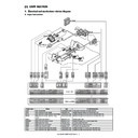
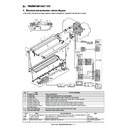
B. Operational descriptions
(1) Charging operation
The screen grid is attached to the main charger unit, and the OPC
drum is charged at a voltage virtually similar to the voltage applied
to the screen grid.
drum is charged at a voltage virtually similar to the voltage applied
to the screen grid.
Main charger grid voltage
(2) Drum surface potential sensor
The front surface potential on the OPC drum is detected after
charging and exposure. The drum surface is detected by potential
sensor to ensure its specified charge level.
The output (DESS) of the drum surface potential sensor is inputted
to the PCU PWB. The main charger grid voltage control signal
(XGBPWM) duty is varied by the PCU PWB so that the OPC drum
surface potential is specified level.
The main charger ON/OFF is controlled by the signal (XMHVREM).
(3) Charger wire cleaning operation
The main charger wire is cleaned by the charger wire cleaner at the
specified interval. The charger wire cleaner is reciprocated once for
one cleaning operation.
The cleaning operation can be also executed with Sim. 6-4.
The charger wire cleaner is driven by the charger wire cleaning
motor (MCCM), and the home position of the charger wire cleaner
is detected by the sensor (MCHPS1).
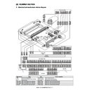
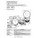
2. Exposure section
A. Operational descriptions
In this section, laser beams are exposed onto the negatively
charged OPC drum surface to form electrostatic latent images.
When laser beams are exposing the CGL of the OPC drum, posi-
tive and negative electric charges are generated. The positive
charged generated on the CGL are attracted and shifted by nega-
tive electric charges on the OPC drum surface. On the other hand,
negative charges are attracted and shifted by positive charges in
the aluminum layer of the OPC drum.
Therefore, positive and negative charges are counterbalanced
each other on the surface and in the aluminum layer of the OPC
drum, reducing positive and negative charges and lowering the
OPC drum surface potential.
In the section where laser beams are not exposed, negative
charges remain.
Through this operation, electrostatic latent images are formed on
the OPC drum surface.
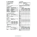
Operation mode
Output voltage
85-sheet machine
95/110-sheet machine
COPY
- 590v
- 610v
PRINTER
- 590v
- 610v
FAX
- 590v
- 610v
MHV
GB
OPC drum
CTL
CGL
Aluminum
layer
CGL
Aluminum
layer
Screen grid
Transfer high
voltage unit
voltage unit
PCU
PWB
PWB
Transfer high voltage unit
MHV
GB
DESS
DESS
Feed back
Feed back
XABPWM/XMHVREM
XABPWM/XMHVREM
DESS
DESS
MCHPS1
MCHPS1
MCCM
MCCM
OPC drum
Laser beam
CTL
CGL
Aluminum
layer
layer
MX-M1100 PHOTOCONDUCTOR SECTION i – 3
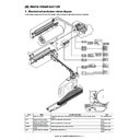
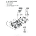
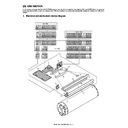
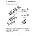
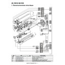
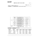
3. Separation section
When paper is not separated from the OPC drum naturally, the separation pawl separates paper mechanically.
A. Electrical and mechanism relation diagram
No.
Name
Function / Operation
1
OPC drum separation pawl
Separates paper from the OPC drum.
2
Separation pawl oscillation shaft drive cam
Converts the drive power of the OPC drum motor into the reciprocating rotation power of the separation
pawl oscillation shaft.
pawl oscillation shaft.
Code
Name
Function / Operation
Type
PSPS
Separation pawl solenoid
Drives the separation pawl.
Solenoid
PSPS
PSPS
1
1
1
1
2
2
1
1
2
2
PCU PWB
1 XPSPS
1
2 XPSPS
2
2
SMR-07V-B/SMP-07V-BC
+24V_A
2
1 +24V_A
SMR-02V-N/SMP-02V-NC
1
XPSPS
36B-PNDZS-1
CN-9
2
1 XPSPS
1
+24V_A
3
2 +24V_A
2
MX-M1100 PHOTOCONDUCTOR SECTION i – 4
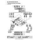
B. Operational descriptions
When paper is not separated from the OPC drum naturally, the separation pawl separates paper mechanically.
The separation pawl is driven by the separation solenoid (XPSPS), and is in contact with the OPC drum when paper passes through the trans-
fer section.
In the other cases, the separation pawl is separated from the OPC drum.
In addition, the separation pawl operates in conjunction with the separation solenoid and oscillates back and forth.
PSPS
PSPS
PSPS
PSPS

