Sharp MX-FNX2 (serv.man8) Service Manual ▷ View online
MX-FNX2/AR-PN1/MX-RBX1 DISASSEMBLY AND ASSEMBLY 6 – 17
7)
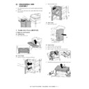
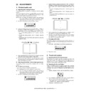
Remove the screw [9].
8)
Disconnect the connector [10] to remove the LED PCB [11].
(4) Waste-Full Photosensor PCB
1)
Remove the punch controller PCB.
2)
Remove the two screws [1] to remove the PCB film [2].
3)
Disconnect the connector [3] to remove the waste-full photo-
sensor PCB [4].
sensor PCB [4].
(5) Waste Full LED PCB
1)
Remove the screw [1].
2)
Disconnect the connector [2] to remove the waste-full LED
PCB [3].
PCB [3].
[11]
[10]
[9]
[2]
[1]
[3]
[2]
[1]
[4]
[3]

