Sharp MX-6500N / MX-7500N (serv.man24) Service Manual ▷ View online
MX-7500N DISASSEMBLY AND ASSEMBLY 10 – 13
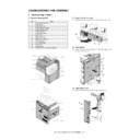
E. Tray paper feed section
(1)
Tandem paper feed tray
1)
Pull out the tandem paper feed tray.
2)
Remove the screw, and remove the tandem paper feed tray.
(2)
Paper feed tray
1)
Pull out the paper feed tray, and lift and remove it.
(3)
Tray paper feed unit
1)
Remove the right vertical transport unit.
2)
Remove the right lower door cover.
3)
Remove the screw, and remove the fulcrum, and the paper
guide.
guide.
4)
Disconnect the connector. Remove the screw, and remove the
tray paper feed unit.
tray paper feed unit.
No.
Name
1
Tandem paper feed tray
2
Paper feed tray
3
Tray paper feed unit
1
1
2
1
1
1
2
3
1
2
2
3
1
MX-7500N DISASSEMBLY AND ASSEMBLY 10 – 14
F. Manual paper feed section
(1)
Manual paper feed tray
1)
Open the right door unit.
2)
Remove the screw, and remove the right door rear cabinet.
3)
Remove the screw, and remove the right door front cabinet
lower.
lower.
4)
Remove the cover. Disconnect the connector.
5)
Remove the shaft. Remove the screw, and remove the manual
paper feed tray.
paper feed tray.
(2)
Manual paper feed unit
1)
Remove the manual paper feed unit.
2)
Disconnect the connector. Remove the screw, and remove the
manual paper feed unit.
manual paper feed unit.
No.
Name
1
Manual paper feed tray
2
Manual paper feed unit
2
1
2
1
1
1
1
2
3
2
2
1
4
3
3
3
1
1
2
MX-7500N DISASSEMBLY AND ASSEMBLY 10 – 15
G. Paper transport section
(1)
Interface unit
1)
Remove the tandem paper feed tray.
2)
Remove the front cover.
3)
Disconnect the connector. Remove the screw, and remove the
interface unit.
interface unit.
(2)
Right vertical transport unit
1)
Remove the waste toner bottle.
2)
Remove the resin E-ring, and remove the right vertical trans-
port unit.
port unit.
(3)
Vertical transport unit
1)
Remove the right vertical transport unit.
2)
Open the right door unit.
3)
Disconnect the connector. Remove the screw, and remove the
vertical transport unit.
vertical transport unit.
(4)
LCC transport unit
1)
Remove the right lower door and the right cabinet lower.
2)
Remove the screw and the connector, and remove the LCC
transport unit.
transport unit.
No.
Name
1
Interface unit
2
Right vertical transport unit
3
Vertical transport unit
4
LCC transport unit
5
PS lower unit
6
PS unit
7
Paper dust cleaner unit
8
Double feed sensor
9
CIS sensor
1
3
2
2
6
7
5
4
2
3
1
1
2
3
1
1
2
2
1
2
3
MX-7500N DISASSEMBLY AND ASSEMBLY 10 – 16
(5)
PS lower unit
1)
Remove the LCC transport unit.
2)
Remove the PS unit.
3)
Remove the screw, and remove the PS lower unit.
(6)
PS unit
1)
Remove the paper dust cleaner unit.
2)
Open the right door unit.
3)
Remove the screw, and remove the cover. Disconnect the con-
nector.
nector.
4)
Remove the screw, and slide the PS unit to the front side and
remove it.
remove it.
(7)
Paper dust cleaner unit
1)
Open the front cover.
2)
Pull out and remove the paper dust removing unit.
(8)
Double feed sensor
NOTE: Sensors and PDFS board must be replaced at the same
time.
1)
Remove the PS unit.
2)
Remove the screw and remove the Double feed sensor cover
and disconnect the connector.
and disconnect the connector.
1
1
2
2
3
3
1
2
1
1
Click on the first or last page to see other MX-6500N / MX-7500N (serv.man24) service manuals if exist.

