Sharp AR-FN1 (serv.man5) Service Manual ▷ View online
2. Explanation of each section
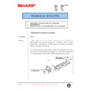
The 3-tray finisher consists of (1)an upper paper transfer section, (2)a
reversion section, (3)a staple tray, (4)an offset tray, and (5)an eleva-
tor section.
reversion section, (3)a staple tray, (4)an offset tray, and (5)an eleva-
tor section.
It has the following functions: Paper discharge to a selected tray,
paper reversion, stapling for paper delivered to the offset tray (3
positions), offset, and elevation. Each function is performed according
to the mode instructed by the copier.
paper reversion, stapling for paper delivered to the offset tray (3
positions), offset, and elevation. Each function is performed according
to the mode instructed by the copier.
A. Upper paper transfer section
1) Paper transfer
By rotating the main driving motor (FM), the transfer rollers in the
finisher are driven.
finisher are driven.
The transfer speed is switched over between the copier speed mode
and the high-speed mode according to the paper discharge mode
and paper size.
and the high-speed mode according to the paper discharge mode
and paper size.
2) Paper entry gate (4)
The paper entry gate (4) is operated by the paper entry sole-
noid(INGSL) to select the upper transfer (outside route) and rever-
sion/short path according to the mode.
noid(INGSL) to select the upper transfer (outside route) and rever-
sion/short path according to the mode.
3) Paper discharge gate 1 (1)
The paper discharge gate 1 (1) is operated by the paper discharge
gate 1 solenoid (OG1SL), to select between the routes for paper
discharge to the tray 1 (10) and transport to the tray 2 (7)/staple tray.
gate 1 solenoid (OG1SL), to select between the routes for paper
discharge to the tray 1 (10) and transport to the tray 2 (7)/staple tray.
4) Paper discharge gate 2 (8)
The paper discharge gate 2 (8) is operated by the paper discharge
gate 2 solenoid (OG2SL) to select between the routes for paper
discharge to the tray 2 (7) and transport to the staple tray.
gate 2 solenoid (OG2SL) to select between the routes for paper
discharge to the tray 2 (7) and transport to the staple tray.
5) Trays 1 (10) and 2 (7) paper discharge operation
When paper is delivered to the trays 1 (10) and 2 (7) at a high-speed
in the 3 tray finisher, the trays 1 and 2 deceleration clutch (13) is
operated at paper delivery timing to decelerate the paper discharge
rollers 1 and 2 in order to align the paper to the trays 1 (10) and 2 (7)
with high accuracy.
in the 3 tray finisher, the trays 1 and 2 deceleration clutch (13) is
operated at paper delivery timing to decelerate the paper discharge
rollers 1 and 2 in order to align the paper to the trays 1 (10) and 2 (7)
with high accuracy.
6) Trays 1 (10) and 2 (7) paper full detection
Whether the trays 1 (10) and 2 (7) are filled with paper is detected by
the tray 1 and 2 paper full sensor.
the tray 1 and 2 paper full sensor.
No.
Signal name
Name
(1)
—
Paper discharge gate
(2)
PFD2
Transfer detecting sensor 2
(3)
PFD1
Transfer detecting sensor 1
(4)
—
Paper entry gate
(5)
INPD
Paper entry sensor
(6)
PFD4
Transfer detecting sensor 4
(7)
—
Tray 2
(8)
—
Paper discharge gate 2
(9)
T2PF
Tray 2 paper full detecting sensor
(10)
—
Tray 1
(11)
PFD3
Transfer detecting sensor 3
(12)
T1PF
Tray paper full sensor
(13)
TI2CL
Trays 1 and 2 deceleration clutch
1)
4)
5)
3)
2)
(13)
(12)
(1)
(2)
(3)
(4)
(5)
(11)
(10)
(8)
(7)
(6)
(9)
Document reversion and
short-cut path
short-cut path
To stapler tray
4 – 3
B. Reversion unit
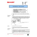
1) Reversion motor (RVM)
The reversion motor is connected to the reversion roller (4).
The paper is pulled into the reversion path by the reversion motor
rotating in forward, and fed into the upper transfer route by the motor
rotating in reverse. When the paper is discharged through the short-
path, its transfer is performed by the reversion roller (4) until the
paper enters the staple tray.
rotating in forward, and fed into the upper transfer route by the motor
rotating in reverse. When the paper is discharged through the short-
path, its transfer is performed by the reversion roller (4) until the
paper enters the staple tray.
2) Reversion pressure release roller
The reversion pressure release roller (3) is pressure released or pres-
surized through ON/OFF control of the reversion roller pressure re-
lease solenoid, to achieve the reversion of the paper at a high speed
without reducing JOB efficiency.
surized through ON/OFF control of the reversion roller pressure re-
lease solenoid, to achieve the reversion of the paper at a high speed
without reducing JOB efficiency.
No.
Signal name
Part name
(1)
RVPD
Reversion paper delivery sensor
(2)
—
Reversion gate
(3)
—
Reversion pressure release roller
(4)
—
Reversion roller
C. Staple tray
1) Jogger motor (JGM)
The jogger motor is driven when the paper is fed into the staple tray,
to operate the jog plates F and R so as to align the sidewise edge of
the paper.
to operate the jog plates F and R so as to align the sidewise edge of
the paper.
2) Puddler (11)
The puddler clutch (PDCL) is turned ON when the paper is fed into
the staple tray, to give the puddler a full turn so as to drop the paper
downward (pusher), thus achieving alignment in the vertical direction.
the staple tray, to give the puddler a full turn so as to drop the paper
downward (pusher), thus achieving alignment in the vertical direction.
3) Pusher motor (PSM)
With the pusher motor rotating, the paper stored inside the staple tray
is lowered from the home position (discharge position) to the stapling
position; after stapling, the paper inside the staple tray is elevated
from the stapling position to the home position.
is lowered from the home position (discharge position) to the stapling
position; after stapling, the paper inside the staple tray is elevated
from the stapling position to the home position.
4) Staple unit movement motor (STUM)
The staple unit is moved to the stapling positions (front, far end, 2
centers) by the staple unit motor.
centers) by the staple unit motor.
5) Short path switching gate (1)
The short path switching gate (1) is operated by the short path
switching solenoid (SPSL), to select the short path to feed paper to
the reversion path and stable tray.
switching solenoid (SPSL), to select the short path to feed paper to
the reversion path and stable tray.
6) Staple tray paper discharge
When the paper delivery roller pressure release clutch (STORCL) is
turned ON, the paper delivery pressure release roller (4) is pressur-
ized through the cam to discharge the paper from the stable tray.
turned ON, the paper delivery pressure release roller (4) is pressur-
ized through the cam to discharge the paper from the stable tray.
7) Paper discharge gate 3 (5)
The paper discharge gate 3 (5) is operated by the paper discharge
gate 3 solenoid (OG3SL) to switch over the routes of paper inside the
staple tray between the paper discharge side and the staple side of
the off-set tray.
gate 3 solenoid (OG3SL) to switch over the routes of paper inside the
staple tray between the paper discharge side and the staple side of
the off-set tray.
8) Tray 3 speed change clutch (8) (2)
The paper discharge rollers 3 and 4 are speed changed to improve
the stackability of stapled paper being discharged to the off-set tray.
the stackability of stapled paper being discharged to the off-set tray.
No.
Signal name
Part name
(1)
—
Short path switching gate
(2)
T3SLCL
Tray 3 speed change clutch
(3)
—
Pusher
(4)
—
Paper delivery pressure release roller
(5)
—
Paper discharge gate 3
(6)
STPD
Staple tray paper detection sensor
(7)
—
Staple unit
(8)
T3ORSL
Tray 3 speed change clutch
(9)
T3OD
Tray 3 paper delivery sensor
(10)
STID
Staple tray paper entry sensor
(11)
—
Puddler
(4)
(2)
(1)
(3)
(1st sheet is reversed
and discharged.)
and discharged.)
(2nd sheet is reversed
and entered.)
and entered.)
Entry
Discharged
Pressure
release
release
(11)
(10)
(9)
(8)
(6)
(5)
(4)
(3)
(2)
(7)
(1)
4 – 4
(Operation of stapling)
Jogging in lateral direction
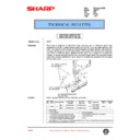
1) The jog plates are moved to the stand-by position before the
paper is fed to the staple tray.
2) Immediately after the paper is fed into the staple tray, the jog plate
is moved to the paper size position to ensure the alignment of the
paper.
paper.
Staple unit movement at the time of stapling (1-point
stapling)
stapling)
1) The stapler unit is moved to the stapling position.
– The number of sheets to be stapled is fed to the staple tray –
2) The pusher (the sheets to be stapled) is lowered the stapling
position.
3) The paper is stapled ... (in the case of 2-point stapling, the action
that is described on the following page is added.)
4) The pusher (the sheets stapled) is elevated to the paper dis-
charge position.
5) After the job, the stapler unit is returned to the home position.
Stapler unit movement at the time of stapling
(2-point stapling action is added.)
(2-point stapling action is added.)
1) The pusher is elevated to the position which makes it possible for
the staple unit to move.
2) The staple unit is moved to the staple position where the 2nd
staple is driven.
3) The pusher (sheets to be stapled) is lowered to the stapling posi-
tion.
4) Sheets are stapled.
5) The staple unit is returned to the 1st staple position.
(After the job is finished, the staple unit is returned to the home
position.)
position.)
D. Off-set tray
1) Off-set motor (3)
When the off-set motor (3) is driven, the tray is shifted sidewise
against the direction in which the sheets are delivered, so that the
sheets discharged into the off-set tray (1) are sorted by the specified
number of sheets. The rotation is unidirectional and controlled by the
crank. The motor is braked to a stop by the off-set home position
sensor (2) turning ON.
No.
Signal name
Part name
(1)
—
Tray 3 (Off-set tray)
(2)
OFHP
OFHP Off-set home position sensor
(3)
OFM
Off-set motor
1)
2)
2)
1)
Jog plate
R
R
Jog plate
F
F
Pusher
Paper size
5)
1)
3)
2)
4)
Pusher
Staple unit
Home
position
position
Paper discharge
position
position
Staple position
ST rail
Staple unit moving
motor
motor
3)
4)
2)
5)
1)
Pusher
Staple unit
moving range
moving range
Staple position
ST rail
Staple unit moving
motor
motor
(3)
(2)
(1)
Moving range
(30 mm)
4 – 5
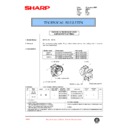
E. Elevator
1) Elevator motor (3)
When the elevator motor (3) is driven, the winding pulley (5) is rotated
in both forward and reverse to wind up the wire (6) stretching verti-
cally so that the tray 3 (off-set tray) is moved up and down. This
allows the discharge of paper at a fixed position according to the
number of sheets to be loaded on the off-set tray.
in both forward and reverse to wind up the wire (6) stretching verti-
cally so that the tray 3 (off-set tray) is moved up and down. This
allows the discharge of paper at a fixed position according to the
number of sheets to be loaded on the off-set tray.
2) Off-set tray full and load detection
When the power is turned ON, the off-set tray lowers to the lower limit
sensor (4) position. Then it elevates until the upper limit sensor (7)
turns ON, while counting the encoder pulses of the elevator motor (3).
sensor (4) position. Then it elevates until the upper limit sensor (7)
turns ON, while counting the encoder pulses of the elevator motor (3).
The volume of paper loaded on the off-set tray is calculated (0 -
100%) by counting the number of pulses from the elevator encoder
(1).
100%) by counting the number of pulses from the elevator encoder
(1).
The off-set tray is judged to be full when both the lower and upper
limit sensors (4, 7) are turned ON.
limit sensors (4, 7) are turned ON.
3) Upper limit sensor solenoid (T3UPSL)
When the paper is discharged from the off-set tray, the upper limit
sensor solenoid is turned on to pull in the actuator so that the sheet
discharged does not ride on the actuator of the upper limit sensor (7).
sensor solenoid is turned on to pull in the actuator so that the sheet
discharged does not ride on the actuator of the upper limit sensor (7).
No.
Signal name
Part name
(1)
—
Elevator motor encoder
(2)
—
Elevator drive unit
(3)
EVM
Elevator motor
(4)
T3DN
Tray 3 lower limit sensor
(5)
—
Winding pulley
(6)
—
Wire
(7)
T3UP
Tray 3 upper limit sensor
3. Basic operation
A. Basic operation flowchart
Fig. 1 Basic operation flowchart
1) Initialization
The finisher is initialized (home positioning of each motor) at the
following timing.
following timing.
•
When the power is turned on.
•
The finisher leaves the copier and when either of the top or bottom
door is opened.
door is opened.
•
When the copier start key is pressed (JOB_START):
•
Recovery action is performed.
(7)
(6)
(5)
(1)
(2)
(4)
(3)
Power ON
Initialization when
powered on
Independent movement
of staple unit
(Staple position)
Independent shifting
Transfer
Off-set trail paper
discharge
JOB_END
Operation when
JAM error occurs
Operation when
door is closed
Stapling
JOB_START
(Offset tray)
4 – 6
Display

