Sharp AR-FN1 (serv.man3) Service Manual ▷ View online
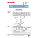
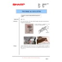
5. Connect the finisher connector.
Cut the connector cover for connection of the finisher relay harness
connector at the copier using nippers.
Then connect the finisher relay harness connector to the connector of
the copier and secure the connector by tightening the screw on the
connector.
connector at the copier using nippers.
Then connect the finisher relay harness connector to the connector of
the copier and secure the connector by tightening the screw on the
connector.
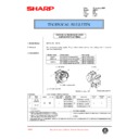
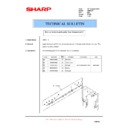
6. Check and adjust the height of the finisher.
•
Put the finisher close to the copier and adjust and
check so that the guide pin of the lock plate enters
smoothly the connecting hole of the finisher.
check so that the guide pin of the lock plate enters
smoothly the connecting hole of the finisher.
•
Since adjustment has been made at shipping, this ad-
justment is basically not needed. If the guide pin
should not be inserted smoothly, adjust the height us-
ing the following procedure.
justment is basically not needed. If the guide pin
should not be inserted smoothly, adjust the height us-
ing the following procedure.
<1> If the guide pin of the lock plate matches the connecting
hole of the finisher:
Push the finisher into the copier.
If the clearance between the copier and finisher is not proper when
the finisher is pushed in, turn the knobs at the lower part of the
finisher to adjust the height so that the clearances of the upper part
and lower part between the copier and finisher are uniform at the
front and back.
If the clearance between the copier and finisher is not proper when
the finisher is pushed in, turn the knobs at the lower part of the
finisher to adjust the height so that the clearances of the upper part
and lower part between the copier and finisher are uniform at the
front and back.
•
If the clearance is narrow at the upper part:
Turn knob A and knob B clockwise so that the clearances at the
upper part and lower part are uniform.
upper part and lower part are uniform.
•
If the clearance is wide at the upper part:
Turn knob A and knob B counterclockwise so that the clearances
at the upper part and lower part are uniform.
at the upper part and lower part are uniform.
<2> If the guide pin of the lock plate does not match the con-
necting hole of the finisher:
Turn the knobs at the lower part of the finisher to adjust the height.
•
If the connecting hole is displaced toward the rear side:
Turn knob B counterclockwise so that the connecting hole matches
the guide pin.
Then, push the finisher into the copier.
If the clearance between the finisher and copier is not proper,
adjust the clearances at the upper part and lower part using proce-
dure <1>.
the guide pin.
Then, push the finisher into the copier.
If the clearance between the finisher and copier is not proper,
adjust the clearances at the upper part and lower part using proce-
dure <1>.
Connector cover
Screw
Connector
Lock plate
Guide pin
(Top view)
Knob B
Knob A
Clearance
Clearance
(Top view)
Guide pin
Knob A
Knob B
2 – 3
•
If the connecting hole is displaced toward the front side:
Turn knob A counterclockwise so that the connecting hole matches
the guide pin.
Then, push the finisher into the copier.
If the clearance between the finisher and copier is not proper,
adjust the clearances at the upper part and lower part using proce-
dure <1>.
the guide pin.
Then, push the finisher into the copier.
If the clearance between the finisher and copier is not proper,
adjust the clearances at the upper part and lower part using proce-
dure <1>.
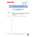
7. Attach the exit tray and tray 3.
Insert the three pawls at the rear side of tray 3 into the holes of the
tray mounting platform and secure the tray using two screws.
Attach the two exit trays to the finisher from the boss at <1>.
tray mounting platform and secure the tray using two screws.
Attach the two exit trays to the finisher from the boss at <1>.
8. Attach the staple cartridge to the staple unit.
Turn the staple unit to face the front.
Insert the staple cartridge into the staple unit until it clicks in
place.
place.
Return the staple unit to face down.
9. Paste the stapling position labels.
For document cover:
Stapling position label A
For SPF:
Stapling position label A
(Top view)
Guide pin
Knob A
Knob B
Exit trays
Screws D
Tray 3
Pawl
Pawl
Pawl
1
2
1
2
3
2 – 4
For ADF/RADF:
Stapling position label B
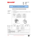
10. Remove the tension spring of exit roller.
1) Pull out the exit unit of the copier until it stops.
2) Remove the 2 exit area cover securing screws and remove the
exit area cover.
3) Remove the 2 transport springs which are attached to the exit
area paper guide.
4) Store the 2 removed transport springs by hanging them on the exit
unit front frame (shown in Fig. 1).
5) Attach the exit area cover to its original position and secure it
using the 2 securing screws.
6) Insert the exit unit to the copier.
3)
Paper exit unit
Fixing screw
Paper exit cover
2 – 5
Display

