Sharp AR-C260 (serv.man10) Service Manual ▷ View online
AR-C260/C260M DESCRIPTIONS OF EACH SECTION 7 - 41
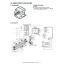
B. Disassembly/assembly/maintenance
a. ORS light emitting PWB
1) Remove the upper cabinet rear cover and the upper cabinet rear
unit.
2) Remove the screw, and remove the document size sensor unit.
Remove the screw and the document size sensor, and remove the
ORS light emitting PWB.
ORS light emitting PWB.
b. OCSW
1) Remove the upper cabinet rear cover and the upper cabinet rear
unit.
2) Remove the connector and the screw, and remove the OCSW.
c. ORS light receiving PWB
1) Remove the FD connection cabinet, the front cabinet upper, the
FD paper exit port cabinet, and the operation panel plate.
2) Remove the connector and the screw, and remove the ORS light
receiving PWB.
d. Operation key PWB
1) Remove the FD connection cabinet, the front cabinet upper, the
FD paper exit port cabinet, and the operation panel plate.
2) Remove the screw, and remove A and B.
3) Remove the screw and the connector, and remove the operation
unit.
4) Remove the screw and remove the operation key PWB.
e. Inverter/LVDS PWB
1) Remove the FD connection cabinet, the front cabinet upper, the
FD paper exit port cabinet, and the operation panel plate.
2) Remove the connector and the screw, and remove the inverter/
LVDS PWB.
A
B
AR-C260/C260M DESCRIPTIONS OF EACH SECTION 7 - 42
7. External fitting
A. Disassembly
(1) Cabinet disassembly 1
1) Open the front cabinet.
2) Remove the front cabinet band. Pull out the slide pin (B), and
remove the front cabinet (C).
(2) Cabinet disassembly 2
1) Remove the front cabinet.
2) Open the left cabinet. Remove the screw and remove the front
frame cover.
(3) Cabinet disassembly 3
1) Remove the screw, and slide the paper exit tray cabinet right to the
right to remove.
(4) Cabinet disassembly 4
1) Remove the screw, and remove the rear cabinet (A). Remove the
screw, and remove the DC power CFM unit (B) and the connector.
Remove the screw, and remove the ROM cover (C) and the rear
connection cabinet (D).
Remove the screw, and remove the ROM cover (C) and the rear
connection cabinet (D).
∗
When assembling, insert the boss in section E into the hole in
the frame.
the frame.
(5) Cabinet disassembly 5
1) Remove the rear cabinet.
2) Remove the screw (A), and slide the front right cabinet (B) upward
to remove. Remove the screw, and slide the connection right cabi-
net (C), the rear right cabinet (D), and the right lower cabinet (E)
upward to remove.
net (C), the rear right cabinet (D), and the right lower cabinet (E)
upward to remove.
(6) Cabinet disassembly 6
1) Remove the rear cabinet.
2) Remove the screw, and remove the FD connection cabinet (A) and
the front cabinet upper (B). Remove the screw, and slide the rear
left cabinet lid (C) and the rear left cabinet (D) upper to remove.
left cabinet lid (C) and the rear left cabinet (D) upper to remove.
C
A
A
B
B
D
A
B
E
C
D
C
A
B
E
A
C
D
B
AR-C260/C260M DESCRIPTIONS OF EACH SECTION 7 - 43
(7) Cabinet disassembly 7
1) Remove the screw, and remove the FD paper exit port cabinet (A)
and the operation panel plate (B).
(8) Cabinet disassembly 8
1) Remove the screw, and remove the upper cabinet rear cover (A).
Remove the connector and the screw, and remove the upper cabi-
net rear unit.
net rear unit.
A
B
A
B
AR-C260/C260M DESCRIPTIONS OF EACH SECTION 7 - 44
8. Others
A. Disassembly/assembly/maintenance
(1) Maintenance target parts
✕
: Check (Clean, replace, or adjust as necessary.)
❍
: Clean
▲
: Replace
∆
: Adjust
✩
: Lubricate
❏
: Shift position
Unit name
No.
Part name
When
calling
50K
100K
150K
200K
250K
300K
350K
400K
Remark
Filters
1
Ozone filter
✕
▲
▲
▲
▲
▲
▲
▲
▲
2
Sub ozone filter
✕
▲
▲
▲
▲
▲
▲
▲
▲
Drive section
3
Gears
✩
✩
✩
✩
✩
✩
✩
✩
✩
4
Belts
✕
✕
✕
✕
✕
✕
✕
✕
✕
Others
5
Sensors
✕
✕
✕
✕
✕
2
5
5
5
5
5
5
5
5
5
5
5
5
5
5
5
5
5
5
5
5
5
5
5
5
5
5
5
3
3
3
3
3
3
3
3
3
3
3
3
3
4
1
Click on the first or last page to see other AR-C260 (serv.man10) service manuals if exist.

