Sharp AR-810 (serv.man11) Service Manual ▷ View online
AR-651/810 IMAGE PROCESSING 7 - 5
0 1 2 3 4 5 6 7 8 9
0 1 2 3 4 5 6 7 8 9
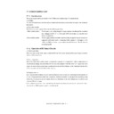
(b) Filtering
This function is enabled by a low-pass filter circuit and a high-pass filter circuit.
•
Low-pass filter circuit
This circuit removes image noise and electrical noise, decreases moire, and realizes high
reproducibility of original by applying an averaging operation on the image signal of the targeted
pixel and those of the pixels positioning next to it.
<Example> The density of the targeted pixel position is “x”. The density of the pixel positions at
the front and back of the targeted pixel are “a” and “b” respectively, “x” is converted to
“ x’ ” through low pass filtering.
When the matrix is (3 x 1):
The above averaging operation is performed for all the pixel positions to accomplish the high
reproducibility of the original.
The following is when low pass filtering is applied on the primary scanning pixel.
•
High-pass filter circuit
The change of the density at the character outline becomes smooth when an original, such as text,
with a great difference in density between the pixels placed next to one another is optically scanned
and output from the CCD. This is caused by the characteristic of the lens and other factors. In this
copier, the process such as the edge enhancement, is applied on the targeted pixel and the pixels
around it to eliminate this phenomenon and realize high reproducibility of the original.
Density
After low-pass filtering
Primary scanning pixel positions
a + b + x
3
x’ =
Original
Image signal
After correction
Low contrast area
Solid black area
Density
Primary scanning pixel positions
a
x
b
AR-651/810 IMAGE PROCESSING 7 - 6
(2) Image memory editing
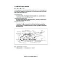
This function performs editing such as enlargement/reduction, mirror imaging, etc. using the line memory.
Pixel data for one line in the primary scanning direction are stored in the line memory and the memory
is renewed at each line.
(a) Enlargement/reduction
The enlargment/reduction is accomplished by using the line memory control function in the process
of the image processing operation.
<Example>
Enlargement
<Example>
Reduction
(b) Mirror imaging
This is accomplished by reading and outputting data from its end.
(3) Edit processing
This function performs trimming, masking and negative/positive reversing.
(a) Trimming
Using rectangular area signals, the image signals inside the rectangular area are left and the other
image signals outside the area are eliminated.
(b) Masking
Using rectangular area signals, the image data inside the rectangular area are erased.
(c) Negative/positive reversing
This function reverses the entire data from negative to positive or vice versa.
1
100%
200%
2
3
4
5
6
7
8
9
10
1
1
2
2
3
3
4
4
5
5
1
100%
50%
2
3
4
5
6
7
8
9
10
1
3
5
7
9
(4) Gamma correction
This function corrects the input/output characteristics of the scanner/printer and adjusts the image
signals so that their input/output characteristics match with the copy mode.
(5) Gradation processing
This function works for genuine reproduction of halftone image such as photographs.
(6) External output system interface
This function controls the output of the output interface between the SLG board and the SYS board
(PWA-F-SYS-340).
AR-651/810 IMAGE PROCESSING 7 - 7
7. 4. PLG Board (PWA-F-PLG-340)
7. 4. 1. Features
(1) The image processing ASIC on the PLG board is controlled by the CPU on the PLG board.
(2) The image processing functions of the PLG board realizes the following functions:
• Smoothing processing
• External input system interface
• Image area control
• Laser related control
7. 4. 2. Functions of image processing circuit
An image processing ASIC mounted on the PLG board enables the following functions:
(1) Smoothing processing
This function removes jaggedness and smoothes character outline of the text images input from the
external input system interface, then outputs them.
(2) External input system interface
This function controls the input interface between the PLG board and the SYS board (PWA-F-SYS-
340).
(3) Image area control
This function sets the effective image area of four directions for the image to be output.
(4) Laser related control
This function controls the APC (Auto Power Control) for the laser diodes.
AR-651/810 IMAGE PROCESSING 7 - 8
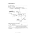
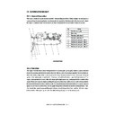
7. 5. Scanning Section
and the optical image data is converted into an electrical signal. This analog signal undergoes the A/D
conversion processing and is changed into a digital signal. The signal then undertakes various corrective
processes necessary for image formation.
The CCD elements convert the optical signal (light) into electrical signal (voltage). (
Chap.6.5.1)
(2) Signal amplification
Amplifies the electrical signals received from the CCD.
(3) A/D conversion
Converts the analog signal into a digital signal.
(4) Shading correction
Shading correction is applied to the signal received front the CCD. (
Chap.6.5.2.)
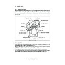
7. 6. Writing Section
The image signal is processed by the PLG board ASIC for the writing operation. The laser is controlled
based on this signal, writing the image data on the drum.
(1) Setting the effective image area ........................ • Top, bottom, left and right margins
(2) Horizontal synchronization signal (H-Sync) ....... • The reference clock signal in the printer section
clock generation section
is synchronized with the H-Sync signal from the
LSU.
(3) Laser drive section ............................................ • The ON/OFF control of the semiconductive laser
and APC (Auto Power Control) control is performed
based on the processed image data.
CCD
Signal
amplification
A/D
conversion
Shading
correction
Next stage
Display

