Sharp AR-810 (serv.man13) Service Manual ▷ View online
AR-651/810 PAPER FEEDING SECTION 9 - 1
9. PAPER FEEDING SECTION
9. 1. General Description
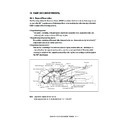
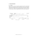
The paper feeding system is for transporting paper set on the cassette, bypass tray and tandem LCF to the
transfer section.
The clutch controls to convey the motor drive to each roller, and each sensor detects the transporting state
of the paper.
9. 2. Functions
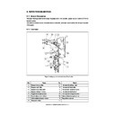
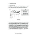
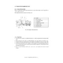
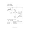
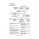
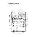
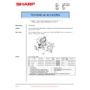
Paper feeding system sectional view (Front side)
No.
Name
No.
Name
1
Bypass pickup roller
9
1st cassette pickup roller
2
Bypass feed roller
10
1st cassette feed roller
3
Bypass separation roller
11
1st cassette separation roller
4
Bypass transport rollers
12
1st cassette feed sensor
5
Registration roller (metal)
13
1st cassette transport sensor
6
Registration roller (rubber)
14
Intermediate transport sensor
7
Intermediate transport rollers
15
Registration sensor
8
Transport rollers
—
1
2
4
5
6
7
8
9
11
10
3
13
12
14
15
AR-651/810 PAPER FEEDING SECTION 9 - 2
(1) Pickup roller
These rollers draw paper off the stack from the bypass tray, cassette or tandem LCF and send it to the
feed roller.
(2) Feed roller
This roller is placed against the separation roller. It transports paper from the pickup roller to the
transport roller.
(3) Separation roller
This roller is placed against the feed roller. When two or more sheets of paper are sent from the pickup
roller, the load of the torque limiter of the separation roller is greater than the frictional force between the
sheets of paper. As a result, the separation roller is stopped and the lower paper is not advanced any
further. When only one sheet of paper is sent from the pickup roller, the separation roller rotates follow-
ing the feed roller.
(4) Transport rollers
These rollers transports the paper sent from the feed roller to the registration roller.
(5) Registration roller
The paper sent from the transport rollers is pushed against the registration roller which aligns its
leading edge of paper. As the correct timing the registration roller rotates to transport the paper to the
transfer section so as to align the leading edge of the paper with the leading edge of the image on the
OPC drum.
(6) Bypass feed sensor
This sensor detects if paper is set in the bypass tray. If it is, bypass feeding takes priority over
cassette feeding.
(7) Cassette empty sensor
This is an emission type sensor that detects the availability of paper in the cassette by using an
actuator. When there is no paper in the cassette, the actuator blocks the light path of the sensor, and
the sensor output in a rates that there is no paper.
(8) Feed sensor, Transport sensor
The feed sensor detects if the leading edge or trailing edge of the paper passed the feed roller. The
transport sensor detects if the leading edge or trailing edge of the paper passed the transport roller.
They also detect jams like misfeeding.
(9) Registration sensor
This sensor detects that the leading edge of paper has reached the registration roller and the trailing
edge of paper has passed the registration roller at the proper time.
AR-651/810 PAPER FEEDING SECTION 9 - 3
(10) Tray-up sensor
This sensor detects the tray position when the paper lift plate of the cassette and tandem LCF is in the
up position.
(11) Bottom sensor
This sensor detects when the paper lift plate is at the lower unit position for the cassette and tandem
LCF.
AR-651/810 PAPER FEEDING SECTION 9 - 4
9. 3. Operation
9. 3. 1. Operation of bypass pickup roller
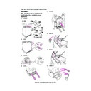
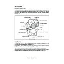
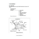
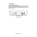
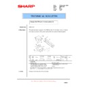
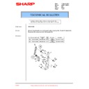
When the bypass pickup solenoid is turned ON, the plunger is pulled and the lever is rotated and lowered.
The pickup arm, which is linked with the lever, is also lowered with the lever by its own weight. When the
bypass pickup solenoid is turned OFF, the pickup arm is brought up by the spring force.
The driving force transmitted through the bypass feed clutch is also transmitted to the bypass feed roller
through the shaft and then to the bypass pickup roller through the timing belt. The roller is rotated by this
driving force.
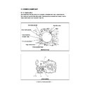
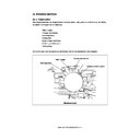
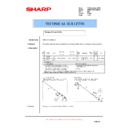
9. 3. 2. Operation of cassette pickup roller
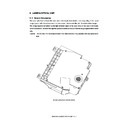
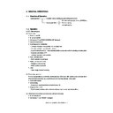
When the cassette is inserted, the protrusion at the rear side of the cassette pushes the lever (a) in the A
direction. Then, the pickup roller and roller holder are lowered by the spring force of (B).
Bypass pickup roller
Spring
Bypass feed roller
a
A
B
Bypass pickup solenoid
Lever
Pickup arm
Shaft

