Sharp AL-1555 (serv.man11) Service Manual ▷ View online
AL-1555 ADJUSTMENTS 9 - 5
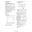
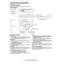
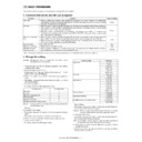
(2) Perform the adjustment in each mode.
1) Execute SIM 46-1.
2) Select the mode to be adjusted with the exposure mode select key.
Set the exposure level to 3 for all adjustment. (Except for the auto
mode.)
mode.)
3) Make a copy.
Check the adjustment level (shown in the above table) of the
exposure test chart (Sharp Gray Scale).
exposure test chart (Sharp Gray Scale).
(When too bright): Decrease the value displayed on the copy quantity
display.
(When too dark):
Increase the value displayed on the copy quantity
display.
display.
* The value can be set in the range of 1 - 99.
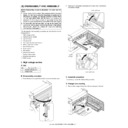
3. High voltage adjustment
A. Main charger (Grid bias)
Note:
• Use a digital multi meter with internal resistance of 10M
Ω
or more
measurement.
• After adjusting the grid LOW output, adjust the HIGH output. Do not
reverse the sequence.
Procedures
1) Set the digital multi meter range to DC700V.
2) Set the positive side of the test rod to the connector CN11-3
(GRID) of high voltage section of the power PWB and set the
negative side to the frame ground (power frame).
negative side to the frame ground (power frame).
3) Execute SIM 8-3. (The main charger output is supplied for 30 sec
in the grid voltage LOW output mode.)
4) Adjust the control volume (VRG2) so that the output voltage is
– 390 ±20V.
5) Execute SIM 8-2. (The main charger output is supplied for 30 sec
in the grid voltage HIGH output mode.)
6) Adjust the control volume (VRG1) so that the output voltage is 580
±12V.
B. DV bias check
Procedures
1) Set the digital multi meter range to DC500V.
2) Set the positive side of the test rod to the connector CN-10-1 (DV
BIAS) and set the negative side to the frame ground (power
frame).
frame).
3) Execute SIM 25-1 to output the developing bias for 30sec, and
check that the output is – 400 ±8V.
Adjustment mode
Exposure mode
display lamp
Sharp gray chart
adjustment level
Auto mode
Auto lamp ON
"3" is slightly copied.
Manual mode
Manual lamp ON
"3" is slightly copied.
Photo mode
Photo lamp ON
"3" is slightly copied.
Manual T/S mode Manual lamp/Photo lamp
ON
"3" is slightly copied.
Auto T/S mode
Auto lamp/Photo lamp ON "3" is slightly copied.
Sharp Gray Scale adjustment level
Non toner
save mode
save mode
Toner save
mode
mode
(1) Mode select key/display
lamp
(2) Exposure level select
key/display lamp
(1)
(2)
1
10
W
2
3
4
5
6
7
8
9
Slightly copied.
Not copied.
1
10
W
2
3
4
5
6
7
8
9
Slightly copied.
Not copied.
Note: • A digital multi meter with internal resistance of 1G
Ω
must be
use for correct check.
• The adjustment volume is locked, and no adjustment can be
made.
VRG1
VRG2
VRDV
AL-1555 ADJUSTMENTS 9 - 6
4. Duplex adjustment
A. Adjusting the paper reverse position in memory
for duplex copying
This step adjusts the front surface printing (odd-number pages of a
document set) in the S-D mode copying and the leading edge position
of an image on even-number pages in the D-S mode.
document set) in the S-D mode copying and the leading edge position
of an image on even-number pages in the D-S mode.
That is, it covers the adjustment of the second surface printing mode
(image loss at the front edge of an image) in which image data is once
stored in memory.
(image loss at the front edge of an image) in which image data is once
stored in memory.
The image data is read, starting from its front end in the document
delivery direction (Reference direction of document setting in the OC
mode)and stored in memory.
delivery direction (Reference direction of document setting in the OC
mode)and stored in memory.
This stored image data is printed starting at the printing start position,
in the order of last-stored data to the first-stored data.
in the order of last-stored data to the first-stored data.
In other words, the front edge image loss of the image can be adjusted
by changing the document read end position.
by changing the document read end position.
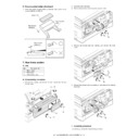
(Adjustment procedure)
1) Preparing test chart (Draw a scale at the rear end of one side of a
sheet of A4 white paper or letter paper)
2) Set the test chart so that the scale is positioned as shown below, in
the S-D mode and the D-S mode.
3) Execute simulation 50-18 to make a copy and check the front edge
image loss at the area where the scale is printed.
Adjust the setting so that the front edge image loss is less than 4.0
mm in the R-SPF mode.
An increase of 1 in setting represents an increase of 0.1 mm in
image loss.
Adjust the setting so that the front edge image loss is less than 4.0
mm in the R-SPF mode.
An increase of 1 in setting represents an increase of 0.1 mm in
image loss.
B. Adjusting trailing edge void in duplex copy mode
This is the adjustment of the first surface printing mode (rear end void)
in duplex copying.
in duplex copying.
In a duplex copying operation, the paper is delivered starting from the
rear end of the first printing surface. It is therefore necessary to make a
void area at the rear end on the first printing surface to prevent paper
jam at the fusing part.
rear end of the first printing surface. It is therefore necessary to make a
void area at the rear end on the first printing surface to prevent paper
jam at the fusing part.
There are two adjustment modes:
1) Image cut rear end void quantity (R-SPF) 50-19(AE)
The size (length) of a document read from the R-SPF is detected,
the image at the trailing edge of the first printing surface is cut to
make a void area. (The adjustment of void quantity at the time
when the cassette paper size is not recognized.)
the image at the trailing edge of the first printing surface is cut to
make a void area. (The adjustment of void quantity at the time
when the cassette paper size is not recognized.)
2) Paper trailing edge void quantity 50-19 (TEXT)
This adjustment is made when the cassette paper size is
recognized. The trailing edge void quantity can be adjusted by
changing the trailing edge image laser OFF timing.
recognized. The trailing edge void quantity can be adjusted by
changing the trailing edge image laser OFF timing.
The paper void quantity should be first adjusted before the image cut
trailing edge void quantity (R-SPF) is adjusted.
trailing edge void quantity (R-SPF) is adjusted.
(Adjustment procedure)
(1) Paper trailing edge void quantity
1) Preparing test chart (Draw a scale at the rear end of one side of a
sheet of A/4 white paper or letter paper)
2) Set the test chart on the document glass as shown below.
3) Using the user simulation [18], set the paper size of the first
cassette.
• Letter paper: 4
• A4 paper: 3
5 10
Scale (S-D mode)
Scale (D-S mode)
5 10
The front edge of the
scale on test chart
scale on test chart
Front edge of paper
Void area
less than 4 mm
2nd printing surface where scale is printed (lower side)
Document guide
The trailing edge has a scale
Table glass
AL-1555 ADJUSTMENTS 9 - 7
4) Execute simulation 50-19 to turn on the TEXT lamp and make the
printing mode in OC-D mode.
Make a copy of the test chart to check the void area of the scale on
the image.
Make a copy of the test chart to check the void area of the scale on
the image.
Adjust the setting so that the void area is 4 - 5 mm. An increase in 1 of
setting represents 0.1 mm in void area.
setting represents 0.1 mm in void area.
(2) Image cut trailing edge void quantity (R-SPF)
1) Set the test chart so that the scale is positioned as shown below.
2) Execute simulation 50-19 to turn on the AE lamp(on the operation
panel) and make the printing mode in the D-D mode.
3) Remove and reinsert the cassette.
Note: Make sure to carry out this step before making a copy during
this adjustment.
4) Make a copy and check the void area of the scale on the image.
Adjust the setting so that the void area is 2 - 4 mm. An increase of
1 in setting represents an increase of 0.1 mm in void area.
l Void position to be checked
1 in setting represents an increase of 0.1 mm in void area.
l Void position to be checked
The trailing edge void on the first printing surface
is shown above.
is shown above.
Paper
Void position to be check
Scale (D-D mode)
Display

