Sharp AL-1000 / AL-1010 (serv.man8) Service Manual ▷ View online
[6] Printing process
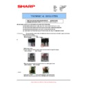
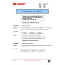
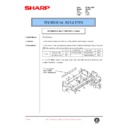
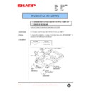
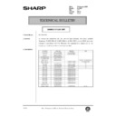
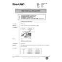
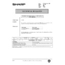
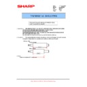
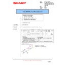
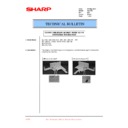
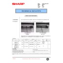
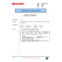
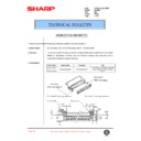
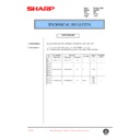
(1) Functional diagram
(Basic operation cycle)
Exposure
Main high voltage unit
Saw tooth
Charge
Drum
Cleaning
Cleaning blade
Waste toner box
Paper release
Fusing
Separation
Heat roller
Heater lamp
Transfer
Transfer charger
Transfer high
voltage unit
voltage unit
Developing
Toner
Developer
Print process
Paper transport route
Semiconductor laser
Manual feed
PS roller
Focus correction lens
Electrode
Synchronization
with drum
Cassette
paper feed
To face
down tray
down tray
(20microns thick)
Aluminium drum
Pigment layer (0.2
to 0.3 microns thick)
to 0.3 microns thick)
An OPC drum is used for the photoconductor.
(Structure of the OPC drum layers)
(Structure of the OPC drum layers)
OPC layer
Main charger
Laser beam
MG roller
Cleaning blade
Drum
Transfer unit
Resist roller
AL-1000/1010
6-1
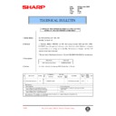
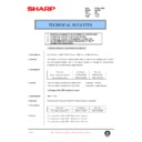
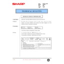
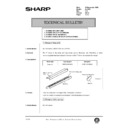
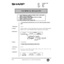
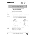
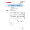
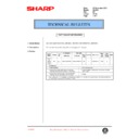
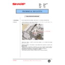
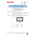
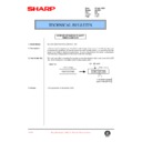
(2) Outline of print process
This printer is a non-impact printer that uses a semiconductor
laser and electrostatic print process. This printer uses an OPC
(Organic Photo Conductor) for its photoconductive material.
First, voltage from the main corona unit charges the drum sur-
face and a latent image is formed on the drum surface using a
laser beam. This latent image forms a visible image on the
drum surface when toner is applied. The toner image is then
transferred onto the print paper by the transfer corona and
fused on the print paper in the fusing section with a combina-
tion of heat and pressure.
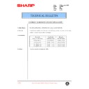
Step-1:
Charge
Step-2:
Exposure
∗
Latent image is formed on the drum.
Step-3:
Developing
Latent image formed on the drum is then changed
into visible image with toner.
Latent image formed on the drum is then changed
into visible image with toner.
Step-4:
Transfer
The visible image (toner image) on the drum is trans-
fered onto the print paper.
The visible image (toner image) on the drum is trans-
fered onto the print paper.
Step-5:
Cleaning
Residual toner on the drum surface is removed and
collected by the cleaning blade.
Residual toner on the drum surface is removed and
collected by the cleaning blade.
Step-6:
Optical discharge
Residual charge on the drum surface is removed, by
semiconductor laser beam.
Residual charge on the drum surface is removed, by
semiconductor laser beam.
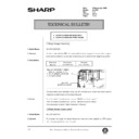
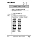
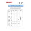
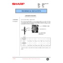
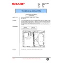
(3) Actual print process
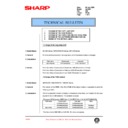
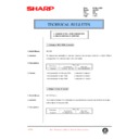
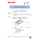
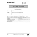
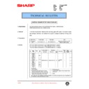
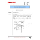
Step-1: DC charge
A uniform negative charge is applied over the OPC drum sur-
face by the main charging unit. Stable potential is maintained
by means of the Scorotron charger.
Positive charges are generated in the aluminum layer.
face by the main charging unit. Stable potential is maintained
by means of the Scorotron charger.
Positive charges are generated in the aluminum layer.
Step-2: Exposure (laser beam, lens)
A Laser beam is generated from the semiconductor laser and
controlled by the print pattern signal. The laser writes onto the
OPC drum surface through the polygon mirrors and lens. The
resistance of the OPC layer decreases for an area exposed by
the laser beam (corresponding to the print pattern signal). The
beam neutralizes the negative charge. An electrostatic latent
image is formed on the drum surface.
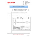
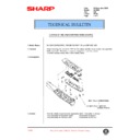
Step-3: Developing (DC bias)
A bias potential is applied to the MG roller in the two com-
ponent magnetic brush developing method, and the toner is
charged negative through friction with the carrier.
Non-image area of the drum surface charged with negative
potential repel the toner, whereas the laser exposed portions
where no negative charges exist, attract the toner. As a result,
a visible image appears on the drum surface.
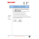
OPC layer
Pigment
layer
layer
Aluminum
drum
drum
OPC layer
Pigment
layer
layer
Aluminum
layer
layer
Drum surface charge
sfter the exposure
sfter the exposure
Non-image area
Image area
Semiconductor laser
Exposure
(semiconductor laser)
(semiconductor laser)
S
N
N
: Carrier (Magnetized particle)
: Toner (Charge negative by friction)
(N) (S) :Permanent magnet
(provided in three locations)
: Toner (Charge negative by friction)
(N) (S) :Permanent magnet
(provided in three locations)
MG
roller
DC
–400V ± 8V
About
DC5.5KV
(–580V/–400V)
AL-1000/1010
6-2
Toner is attracted over the shadowed area because of the
developing bias.
developing bias.
Step-4: Transfer
The visible image on the drum surface is transferred onto the
print paper by applying a positive charge from the transfer
corona to the backside of the print paper.
print paper by applying a positive charge from the transfer
corona to the backside of the print paper.
Step-5: Separation
Since the print paper is charged positively by the transfer
corona, it is discharged by the separation corona. The separa-
tion corona is connected to ground.
corona, it is discharged by the separation corona. The separa-
tion corona is connected to ground.
Step-6: Cleaning
Toner remaining on the drum is removed and collected by the
cleaning blade. It is transported to the waste toner collecting
section in the cleaning unit by the waste toner transport roller.
cleaning blade. It is transported to the waste toner collecting
section in the cleaning unit by the waste toner transport roller.
Step-7: Optical discharge (Semiconductor laser)
Before the drum rotation is stopped, the semiconductor laser is
radiated onto the drum to reduce the electrical resistance in the
OPC layer and elimate residual charge, providing a uniform
state to the drum surface for the next page to be printed.
When the electrical resistance is reduced, positive charges on
the aluminum layer are moved and neutralized with negative
charges on the OPC layer.
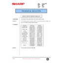
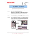
Charge by the Scorotron charger
Function
The Scorotron charger functions to maintain the surface poten-
tial of the drum even at all times which. It is used to control the
surface potential regardless of the charge characteristics of the
photoconductor.
tial of the drum even at all times which. It is used to control the
surface potential regardless of the charge characteristics of the
photoconductor.
Basic function
A screen grid is placed between the saw tooth and the
photoconductor. A stable voltage is added to the screen grid to
maintain the corona current on the photoconductor.
As the photoconductor is charged by the saw tooth from the
main corona unit, the surface potential increases. This in-
creases the current flowing through the screen grid. When the
photoconductor potential nears the grid potential, the current
turns to flow to the grid so that the photoconductor potential can
be maintained at a stable level.
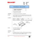
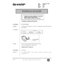
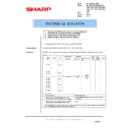
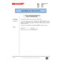
Process controlling
Function
The print pattern signal is converted into an invisible image by
the semiconductor laser using negative to positive (reversible)
developing method. Therefore, if the developing bias is added
before the drum is charged, toner is attracted onto the drum. If
the developing bias is not added when the drum is charged, the
carrier is attracted to the drum because of the strong electros-
tatic force of the drum.
To avoid this, the process is controlled by adjusting the drum
potential and the grid potential of the Scorotron charger.
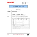
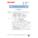
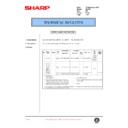
Basic function
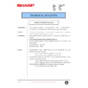
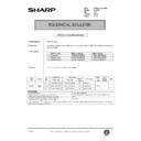
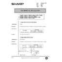
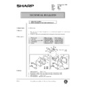
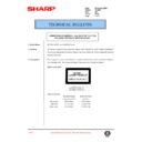
Voltage added to the screen grid can be selected, high and low.
To make it easily understood, the figure below shows voltage
transition at the developer unit.
To make it easily understood, the figure below shows voltage
transition at the developer unit.
-600
0
Toner attract
potential
potential
D
rum su
rfa
c
e
po
te
n
tia
l
Non-image area
Developing bias
Image area
Residual potential (-50 to -100V)
Charge
Exposure
Developing
Transfer
Discharge
Charge
Time
-400
Semiconductor laser
0
START
STOP
Print potentioal
Toner attract
potential
potential
2)
3)
1)
Low
4)
High
Drum potential
Developing bias
Time
About DC 5.2kV
AL-1000/1010
6-3
Start
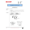
1) Because the grid potential is at a low level, the drum poten-
tial is at about –400V. (Carrier may not be attracted though
the carrier is pulled towards the drum by the electrostatic
force of –400V.
the carrier is pulled towards the drum by the electrostatic
force of –400V.
2) Developing bias ( –400V) is applied when the photoconduc-
tor potential is switched from LOW to HIGH.
3) Once developing bias (–400V) is applied and the photo con-
ductor potential rises to HIGH, toner will not be attracted to
the drum.
the drum.
Stop
The reverse sequence takes place.
Retaining developing bias at an abnormal occurrence
Function
The developing bias will be lost if the power supply was
removed during print process. In this event, the drum potential
slightly abates and the carrier makes deposits on the drum be-
cause of strong static power. To prevent this, the machine in-
corporates a function to retain the developing bias for a certain
period and decrease the voltage gradually against possible
power loss.
Basic function
Normally, the developing bias voltage is retained for a certain
time before the drum comes to a complete stop if the machine
should stop before completing the normal print cycle. The
developing bias can be added before resuming the operation
after an abnormal interruption. Therfore, carrier will not make a
deposit on the drum surface.
AL-1000/1010
6-4
Display

