Sharp LL-T1810A (serv.man3) Service Manual ▷ View online
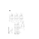
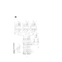
WAVE FORM 17 : OSD COLOR DATA
(13, 15, 17 pins of IC31)
Display Screen : All black pattern OSD menu display
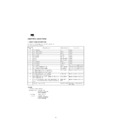
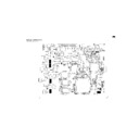
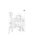
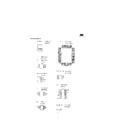
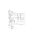
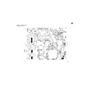
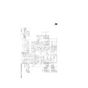
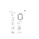
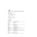
2. CIRCUIT DIAGRAM
Main board (Ver.7)
Sheet No.
Description
1
RGB signal input
2
Synchronizing separator
3
A/D converter and PLL circuit
4
ASIC circuit
5
SGRAM circuit
6
Microprocessor
7
LCD output connector circuit
8
Power supply circuit
DC jack board
Sheet No.
Description
1
DC jack and fuse circuit
LED & SW board
Sheet No.
Description
1
LED and switch circuit
D-sub board
Sheet No.
Description
1
D-Sub connector and DDC circuit
Display

