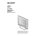
Sharp LL-T15S1 (serv.man9) Service Manual ▷ View online
nThe connector pin
Number
Function
1
Red video signal input
2
Green video signal input
3
Blue video signal input
4
N.C.
5
N.C.
6
For red video signal GND
7
For green video signal GND
8
For blue video signal GND
9
DDC + 5V
10
N.C.
11
GND
12
DDC data
13
For H-sync signal input
14
For V-sync signal input
15
DDC clock
■
Power management
The monitor is based on VESA DPMS (Display Power Management
Signaling).
Signaling).
To activate the monitor’s Power Management function, both the video
card and the computer must conform to the VESA DPMS standard.
card and the computer must conform to the VESA DPMS standard.
DPMS
mode
Screen
H-sync
V-sync
ON
Display on
31W
Yes
Yes
STANDBY
Display off
5W
No
Yes
SUSPEND
Yes
No
OFF
No
No
■
DDC (Plug & Play)
This monitor supports the VESA DDC (Display Data Channel) stand-
ard.
ard.
DDC is a signal standard for carrying out Plug & Play functions be-
tween the monitor and PC. It transfers information such as resolution
between the monitor and PC. You can use this function if your PC is
DDC compliant and if it is set so that it can detect the Plug & Play
monitor.
tween the monitor and PC. It transfers information such as resolution
between the monitor and PC. You can use this function if your PC is
DDC compliant and if it is set so that it can detect the Plug & Play
monitor.
There are many varieties of DDC due to the differences between
systems. This monitor works with DDC1 and DDC2B.
systems. This monitor works with DDC1 and DDC2B.
2. PRODUCT DESCRIPTION
1.
MENU button
This button is used to pop-up, select and close the OSD Menu.
2.
SELECT button
Selects the menu option to be adjusted.
3.
buttons
When the On Screen Display (OSD) Menu is displayed:
These buttons are used to increase or decrease the value of a
selected option.
When the OSD Menu is not displayed:
These buttons are used to adjust backlight brightness.
These buttons are used to increase or decrease the value of a
selected option.
When the OSD Menu is not displayed:
These buttons are used to adjust backlight brightness.
4.
BRIGHT button
The brightness sensor measures the brightness of the surround-
ing environment and automatically adjusts to the right bright-
ness.
ing environment and automatically adjusts to the right bright-
ness.
5.
Power LED
This LED is lit green when in use and orange when in power-
saving mode.
saving mode.
6.
Power button
Pressing this button turns the power on. (After turning the power
on, it may take a little time before the screen displays.)
Press the button again to turn the power off.
on, it may take a little time before the screen displays.)
Press the button again to turn the power off.
7.
Speakers
Audio entering via the monitor and the external device con-
nected to the monitor can be heard.
nected to the monitor can be heard.
8.
Brightness sensor
Measures the brightness of the surrounding environment.
9.
Microphone terminal
A microphone (to be purchased separately) can be connected
here.
here.
10. Headphone terminal
Headphones (to be purchased separately) can be connected
here.
here.
11. Audio input terminal
A computer’s audio output terminal can be connected here. (The
audio cable included should be used.)
audio cable included should be used.)
12. Microphone output terminal
A computer’s microphone terminal can be connected here. (The
audio cable included should be used.)
audio cable included should be used.)
13. Power terminal
Connect the AC adapter (included) here.
14. RGB signal cable
Connects to the computer’s analog RGB output terminal.
15. Ventilation openings
Note: Never block the ventilation openings as this may lead to
overheating inside the monitor and result in malfunction.
overheating inside the monitor and result in malfunction.
5
4
3
2
1
15
14
13
12
11
10
9
8
7
6
Mini D-sub connector with 15 pins
1 2
3
4 5
7
8
9
6
10
11
12
13
14
15
Front View
Left side
surface
Rear view
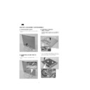
Standing up and adjusting the monitor
CAUTION!
·
Be sure to hold the frame of monitor only. Pressure from hands on
the LCD panel could cause damage.
the LCD panel could cause damage.
Standing up the monitor
Press down on the stand and lift up the top section of the monitor.
Adjusting the monitor
Lightly holding both sides of the monitor, adjust it to a suitable viewing
angle.
angle.
Folding up the monitor
(when packing it away)
(when packing it away)
Except when folding away the monitor to transport it, do not fold down
the monitor. Unnecessarily folding and unfolding the monitor could
lead to malfunction.
the monitor. Unnecessarily folding and unfolding the monitor could
lead to malfunction.
1. Remove the AC adapter.
2. If carrying out adjustments to the monitor, place it upright.
3. While pressing the rear lock disable button
, gently fold back the
monitor
.
25
3
1
2
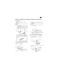
CHAPTER 2. CONNECTION, ADJUSTMENT, OPERATION AND FUNCTIONS
1. CONNECTION
1-1. Connecting the monitor to a Computer
(PC etc.)
When connecting, ensure that both the monitor and computer are
switched off.
switched off.
Note: Do not overly bend the cable or add extension cords as this
could lead to malfunction.
Using the audio cable included, the computer’s audio output terminal
or a microphone terminal can be connected.
or a microphone terminal can be connected.
Note: Do only connect cables less than 3m to the LL-T15S1.
1-2. Connecting the monitor to headphones and a
microphone
Headphones and a microphone (both to be purchase separately) can
be connected here.
be connected here.
Note: Do not overly bend the cable or add extension cords as this
could lead to malfunction.
Note:
·
Do only connect cables less than 3m to the LL-T15S1.
·
When the headphones are connected, no sound can be
heard from the monitor speakers.
heard from the monitor speakers.
1-3. Connecting the monitor to a power source
Before connecting, first turn off the monitor’s main power switch.
Note: Do not overly bend the cable or add extension cords as this
could lead to malfunction.
1. Connect the AC adapter to the monitor’s power terminal
2. Attach the power cord to the AC adapter and place the power plug
into the AC terminal
Firmly insert the analog RGB output terminal
(mini D-sub 15 pin with 3 rows) then tighten the
screws each side.
(mini D-sub 15 pin with 3 rows) then tighten the
screws each side.
RGB cable
If connecting to a D-sub 15 pin 2 row Apple Power
Macintosh, attach a Macintosh conversion adapter
(to be purchased separately) to the RGB signal
cable.
Macintosh, attach a Macintosh conversion adapter
(to be purchased separately) to the RGB signal
cable.
Macintosh conversion adapter
RGB signal cable
After connecting the adapter, tighten
the screws on each side to fix into place.
After connecting the adapter, tighten
the screws on each side to fix into place.
Audio input
terminal
terminal
Microphone
output terminal
output terminal
Audio cable
PC (Microphone terminal)
PC (Audio output terminal)
Microphone
Headphones
Headphone
terminal
terminal
Microphone
terminal
terminal
Power terminal
AC adapter
Power cord
2. POWER ON/OFF
2-1. Turning the power on
1. Turn on the computer.
2. Press the monitor’s power button.
The power LED will be lit green, and the screen will display an
image
image
Note: When setting up this monitor for the first time or after having
changed an aspect of the current system, perform an automat-
ic screen adjustment before use.
ic screen adjustment before use.
2-2. Turning the power off
1. Turn the computer off.
2. Press the monitor’s power button.
The Power LED will disappear.
■
Installing set-up information
Depending on the computer or OS, it may be necessary to use the
computer to operate the installation of monitor set-up information etc.
If so, follow the steps below to install the monitor set-up information.
computer to operate the installation of monitor set-up information etc.
If so, follow the steps below to install the monitor set-up information.
Notes:
·
Depending on the computer type, command names and
methods may differ. Please follow the computer’s own op-
eration manual while reading this.
methods may differ. Please follow the computer’s own op-
eration manual while reading this.
·
This explanation assumes that the floppy disk drive is "A
drive". If the floppy disk drive of your computer is not "A
drive", please read the below substituting the floppy disk
drive you are using in place of "A drive" or "A".
drive". If the floppy disk drive of your computer is not "A
drive", please read the below substituting the floppy disk
drive you are using in place of "A drive" or "A".
For Windows95
Installing monitor set-up information into Windows95.
This explanation assumes that the floppy disk drive is "A drive".
1.
Place the Monitor Settings Adjustment Disk (provided) into the
computer’s A drive.
computer’s A drive.
2.
Click on the [Start] button. From [Settings], choose [Control
Panel].
Panel].
3.
Double click on [Display].
4.
Click on [Settings], [Advanced Properties], and [Monitor], then
[Change].
[Change].
5.
Click on [Have Disk], confirm that [Copy manufacturer’s files
from:] is [A:] then click [OK].
from:] is [A:] then click [OK].
6.
Confirm that the monitor details are selected, and click [OK].
7.
Check that the monitor details are displayed, then click [Apply].
8.
Click [OK], and close the window.
9.
Remove the Monitor Settings Adjustment
Disk from the A drive.
Disk from the A drive.
For Windows98
Installing monitor set-up information into Windows98.
If the "Add New Hardware Wizard" has appeared:
(This explanation assumes that the floppy disk drive is "A drive")
If the "Add New Hardware Wizard" has appeared:
(This explanation assumes that the floppy disk drive is "A drive")
1.
Place the Monitor Settings Adjustment Disk (provided) into the
computer’s A drive.
computer’s A drive.
2.
Click [Next].
3.
Check [Display a list of all the drivers in a specific location, so
you can select the driver you want.], then click [Next].
4.
When [Models] is displayed, click on [Have Disk], confirm that
[Copy manufacturer’s files from:] is [A:], and click [OK].
[Copy manufacturer’s files from:] is [A:], and click [OK].
5.
Confirm that the monitor details are selected, then click [Next],
[Next], and [Finish]. If the "Add New Hardware Wizard" appears,
repeat the installation commands beginning from 2 above.
[Next], and [Finish]. If the "Add New Hardware Wizard" appears,
repeat the installation commands beginning from 2 above.
6.
Remove the Monitor Settings Adjustment Disk from the A drive.
If the "Add New Hardware Wizard" has not appeared:
(This explanation assumes that the floppy disk drive is "A drive")
(This explanation assumes that the floppy disk drive is "A drive")
1.
Place the Monitor Settings Adjustment Disk in the computer’s A
drive.
drive.
2.
Click on the [Start] button. From [Settings], choose [Control
Panel].
Panel].
3.
Double click on [Display].
4.
Click on [Settings], [Advanced] and [Monitor].
5.
In [Options], check [Automatically detect Plug & Play monitors]
and click on [Change].
and click on [Change].
6.
Click [Next].
7.
Click on [Display a list of all the drivers in a specific location, so
you can select the driver you want.], then click [Next].
you can select the driver you want.], then click [Next].
8.
When [Models] is displayed, click on [Have Disk], confirm that
[Copy manufacturer’s files from:] is [A:], and click [OK].
[Copy manufacturer’s files from:] is [A:], and click [OK].
9.
Confirm that the monitor details are selected, then click [Next],
[Next], and [Finish].
[Next], and [Finish].
10. Check that the monitor details are displayed, then click [Apply].
11. Click [OK], and close the window.
12. Remove the Monitor Settings Adjustment Disk from the A drive.
For Windows2000
Installing monitor set-up information into Windows2000.
This explanation assumes that the floppy disk drive is "A drive".
1.
Place the Monitor Settings Adjustment Disk (provided) into the
computer’s A drive.
computer’s A drive.
2.
Click on the [Start] button. From [Settings], choose [Control
Panel].
Panel].
3.
Double click on [Display].
4.
Click on [Settings], [Advanced] and [Monitor].
5.
Click on [Properties], [Driver] and [Update Driver].
6.
When [Upgrade Device Driver Wizard] appears, click [Next].
7.
Check [Display a list of the known drivers for this device so that I
can choose a specific driver] and click [Next].
can choose a specific driver] and click [Next].
8.
When [Models] is displayed, click on [Have Disk], confirm that
[Copy manufacturer’s files from:] is [A:], and click [OK].
[Copy manufacturer’s files from:] is [A:], and click [OK].
9.
Select the monitor from the list displayed and click [Next].
10. Click [Next], confirm that the monitor’s name appears on the
screen, and click [Finish]. If [Digital Signature Not Found] ap-
pears, click [Yes].
pears, click [Yes].
11. Click on [Close].
12. Click [OK], and close the window.
13. Remove the Monitor Settings Adjustment Disk from the A drive.
Power LED
Power button

