Sharp LL-T1520 (serv.man5) Service Manual ▷ View online
PC-UM10M
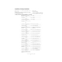
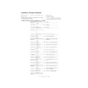
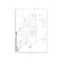
LL-T1520-H/B LL-T1620-H/B TROUBLE SHOOTING
4 – 2
(No)
(Yes)
(Yes)
(No)
(Yes)
Check the power unit, the power cable, their
connection, the DC+12V power line, and IP1.
connection, the DC+12V power line, and IP1.
Is CN10-6P at DC+1.0V or below when the
brightness is maximum ?
brightness is maximum ?
Is the inverter PWB normal ?
Check the lamp in the LCD module.
Replace the inverter PWB unit.
(No)
(Yes)
(No)
Is FB23 at DC+12V ?
Is CN10-5P at H level (DC+3.3V) ?
Check IC16 peripheral circuits.
Check BLON signal and CN10 peripheral
circuits.
circuits.
(No)
(Yes)
(No)
(Yes)
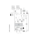
Check the analog signal cable, CN2
peripheral, and IC peripheral circuits.
peripheral, and IC peripheral circuits.
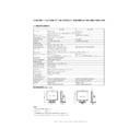
Is CN12-1P at DC+12V ? (LL-T1620H/B only)
Check IP4 and IC25 peripheral circuits.
(Yes)
(No)
Is CN9-39P at DC+5V ? (LL-T1520H/B only)
Check IP2 and IC25 peripheral circuits.
(No)
Are signals at IC13-17, 24, 40P normal ?
Are signals at R19 and R71 normal ?
Check CN2, IC5, and IC13 peripheral circuits.
2
3
(Yes)
(No)
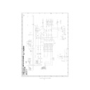
Is the signal between IC13 and CN9,C11 normal ?
(LL-T1520H/B only)
(LL-T1520H/B only)
Check IC13, CN9, and 11 peripheral circuits.
(Yes)
(No)
Is the signal between IC13 and IC27 normal ?
(LL-T1620H/B only)
Check IC13 and IC27 peripheral circuits.
(Yes)
(No)
Is the signal between IC27 and CN12 normal ?
(LL-T1620H/B only)
Check IC27 and CN12K peripheral circuits.
(Yes)
(No)
Are the cables of the LCD unit normal ?
Check the cables and related parts.
(Yes)
Replace the LCD unit.
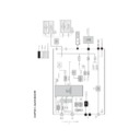
Display

