Sharp R-85STMA (serv.man5) Service Manual ▷ View online
R85STMA
5 – 2
[3] GRILL COOKING CONDITION
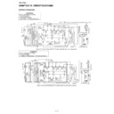
1. TOP GRILL (Figure O-3)
In this condition the food is cooked by the top grill heating element.
Programme the desired cooking time by touching the TIME keys and
touch the GRILL key once. When the START key is touched, the fol-
lowing operations occur:
Programme the desired cooking time by touching the TIME keys and
touch the GRILL key once. When the START key is touched, the fol-
lowing operations occur:
1. The numbers on the digital readout start the count down to zero.
2. The oven lamp, cooling fan motor and turntable motor are ener-
gized.
3. The relay RY3 is energized and the main supply voltage is applied
to the top grill heating element.
4. Now, the food is cooked by the top grill heating element.
2. BOTTOM GRILL (Figure O-3b)
In this condition the food is cooked by bottom grill heating element
energy. Programme the desired cooking time by touching the TIME
keys and touch the GRILL key twice. When the START key is touched,
the following operations occur:
energy. Programme the desired cooking time by touching the TIME
keys and touch the GRILL key twice. When the START key is touched,
the following operations occur:
1. The numbers on the digital readout start the count down to zero.
2. The oven lamp, cooling fan motor and turntable motor are ener-
gized.
3. The relay RY4 is energized and the main supply voltage is applied
to the bottom grill heating element.
4. Now, the food is cooked by the bottom grill heating element.
3. TOP AND BOTTOM GRILLS (Figure O-3c)
In this condition the food is cooked by top and bottom grill heating ele-
ments energy. Programme the desired cooking time by touching the
TIME keys and touch the GRILL key three times. When the START
key is touched, the following operations occur:
ments energy. Programme the desired cooking time by touching the
TIME keys and touch the GRILL key three times. When the START
key is touched, the following operations occur:
1. The numbers on the digital readout start the count down to zero.
2. The oven lamp, cooling fan motor and turntable motor are ener-
gized.
3. The relay RY4 is energized and the main supply voltage is applied
to the bottom grill heating element.
4. The relay RY3 is energized and the main supply voltage is applied
to the top grill heating element.
5. Now, the food is cooked by the top and bottom grill heating ele-
ments.
[4] CONVECTION COOKING CONDITION
1. PRE-HEATING (Figure O-4)
Programme the desired convection temperature by touching
CONV.(
CONV.(
°C) key. When the START key is touched, the following opera-
tions occur:
1. The coil shut-off relays RY1 and RY6 are energized, the oven lamp,
cooling fan motor and turntable motor are turned on.
2. The coil shut-off relays RY3 and RY4 are energized by control unit
and the main supply voltage is added to the top and bottom heating
elements.
elements.
3. When the oven temperature reaches the selected pre-heat temper-
ature, the following operations occur:
1) The coil shut-off relays RY3 and RY4 are energized by control
unit temperature circuit and thermistor, opening the circuit to the
top and bottom grill heating elements.
top and bottom grill heating elements.
2) The oven will continue to function for 30 minutes, turning the top
and bottom heating elements on and off, as needed to maintain
the selected pre-heat temperature. The oven will shut-down
completely after 30 minutes.
the selected pre-heat temperature. The oven will shut-down
completely after 30 minutes.
2. CONVECTION COOKING (Figure O-4)
When the pre-heat temperature is reached, a beep signal will sound
indicating that the holding temperature has been reached in the oven
cavity. Open the door and place the food to be cooked in the oven.
Program desired cooking time by touching the TIME keys and program
convection temperature by touching the CONV.(
indicating that the holding temperature has been reached in the oven
cavity. Open the door and place the food to be cooked in the oven.
Program desired cooking time by touching the TIME keys and program
convection temperature by touching the CONV.(
°C) key. When the
START key is touched, the following operations occur:
1. The numbers on the digital readout start the count down to zero.
2. The oven lamp, cooling fan motor, turntable motor and convection
motor are energized.
NOTE: When the convection temperature 40
°C is selected, the con-
vection motor is not energized.
3. The relays RY3 and RY4 are energized (if the cavity temperature is
lower than selected temperature) and the main supply voltage is
applied to the top and bottom heating elements to return to the
selected cooking temperature.
applied to the top and bottom heating elements to return to the
selected cooking temperature.
4. Upon completion of the cooking time, the audible signal will sound,
and the oven lamp, turntable motor, cooling fan motor, convection
motor, top and bottom heating elements are de-energized. At the
end of convection cycle, if the cavity air temperature rise above
120
motor, top and bottom heating elements are de-energized. At the
end of convection cycle, if the cavity air temperature rise above
120
°C, the circuit to the relay RY6 will be maintained (by the ther-
mistor circuit) to continue operation of the cooling fan motor until
temperature drops below 105
temperature drops below 105
°C, at that time the relay RY6 will be
de-energized, turning off the fan motor.
[5] DUAL COOKING CONDITION
1. MICROWAVE AND CONVECTION (Figure O-5a)
Programme the desired cooking time by touching the TIME keys.
Touch the COMBI key once. Select the convection temperature by
touching the CONV.(
Touch the COMBI key once. Select the convection temperature by
touching the CONV.(
°C) key. And select the microwave power level by
touching the MICRO POWER key. When the START key is touched,
the following operations occur:
the following operations occur:
1. The numbers on the digital readout start the count down to zero.
2. The oven lamp, cooling fan motor, turntable motor and convection
motor are energized.
3. The relay RY3 will be energized and the main supply voltage is
applied to the top grill heating element.
4. The relay RY4 is energized (if the cavity temperature is lower than
selected temperature) and the main supply voltage is applied to the
bottom heating element.
bottom heating element.
5. The relay RY2 is energized and the microwave energy is generated
by magnetron.
6. Now, the food is cooked by microwave and convection energy
simultaneously.
2. MICROWAVE AND TOP GRILL (Figure O-5b)
Programme the desired cooking time by touching the TIME keys.
Touch the COMBI key twice. Select the microwave power level by
touching the MICRO POWER key. When the START key is touched,
the following operations occur:
Touch the COMBI key twice. Select the microwave power level by
touching the MICRO POWER key. When the START key is touched,
the following operations occur:
1. The numbers on the digital readout start the count down to zero.
2. The oven lamp, cooling fan motor and turntable motor are ener-
gized.
3. The relay RY3 is energized and the main supply voltage is applied
to the top grill heating element.
4. The relay RY2 is energized and the microwave energy is generated
by magnetron.
5. Now, the food is cooked by microwave and top grill simultaneously.
R85STMA
5 – 3
3. MICROWAVE AND BOTTOM GRILL (Figure O-5c)
Programme the desired cooking time by touching the TIME keys.
Touch the COMBI key three times. Select the microwave power level
by touching the MICRO POWER key. When the START key is
touched, the following operations occur:
Touch the COMBI key three times. Select the microwave power level
by touching the MICRO POWER key. When the START key is
touched, the following operations occur:
1. The numbers on the digital readout start the count down to zero.
2. The oven lamp, cooling fan motor and turntable motor are ener-
gized.
3. The relay RY4 is energized and the main supply voltage is applied
to the bottom grill heating element.
4. The relay RY2 is energized and the microwave energy is generated
by magnetron.
5. Now, the food is cooked by microwave and bottom grill simulta-
neously.
[6] ON/OFF TIME RATIO
In grill cooking, convection cooking or dual cooking, the top heater,
bottom heater or magnetron operate within a 48 second time base.
The following table is the ON / OFF time ratio at each power output of
the top heaters, bottom heater or magnetron.
bottom heater or magnetron operate within a 48 second time base.
The following table is the ON / OFF time ratio at each power output of
the top heaters, bottom heater or magnetron.
POWER OUTPUT
ON TIME
OFF TIME
100%
48 sec.
0 sec.
70%
36 sec.
12 sec.
50%
26 sec.
22 sec.
30%
16 sec.
32 sec.
10%
8 sec.
40 sec.
Display

