Sharp CD-MD3000 (serv.man10) Service Manual ▷ View online
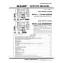
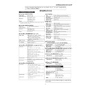
CD-MD3000H/CD-MD3000W
CONTENTS
Page
SAFETY PRECAUTION OF MD SECTION FOR SERVICE MANUAL .............................................................................. 2
SAFETY PRECAUTION OF CD SECTION FOR SERVICE MANUAL (FOR CD-MD3000H) ........................................... 3
IMPORTANT SERVICE NOTES (CD-MD3000H FOR U.K. ONLY) .................................................................................. 3
SAFETY PRECAUTION OF CD SECTION FOR SERVICE MANUAL (FOR CD-MD3000W) ............................................ 4
VOLTAGE SELECTION (FOR CD-MD3000W ONLY) ....................................................................................................... 4
SPECIFICATIONS ............................................................................................................................................................. 5
NAMES OF PARTS ........................................................................................................................................................... 6
OPERATION MANUAL ...................................................................................................................................................... 9
DISASSEMBLY ................................................................................................................................................................ 16
REMOVING AND REINSTALLING THE MAIN PARTS ................................................................................................... 20
CD CHANGER MECHANISM MAIN BASE PARTS ASSEMBLING/ADJUSTING PROCEDURE ................................... 23
ADJUSTMENT ................................................................................................................................................................. 30
TEST MODE .................................................................................................................................................................... 32
EEPROM WRITING PROCEDURE ................................................................................................................................. 43
ERROR MESSAGE LIST ................................................................................................................................................. 44
NOTES ON SCHEMATIC DIAGRAM .............................................................................................................................. 46
BLOCK DIAGRAM ........................................................................................................................................................... 47
SCHEMATIC DIAGRAM .................................................................................................................................................. 54
WIRING SIDE OF P.W.BOARD ....................................................................................................................................... 70
TYPES OF TRANSISTOR AND LED ............................................................................................................................... 84
VOLTAGE ........................................................................................................................................................................ 84
WAVEFORMS OF CD CIRCUIT ...................................................................................................................................... 85
WAVEFORMS OF MD CIRCUIT ..................................................................................................................................... 86
TROUBLESHOOTING ..................................................................................................................................................... 88
FUNCTION TABLE OF IC ................................................................................................................................................ 94
WIRING OF PRIMARILY SUPPLY LEADS (CD-MD3000H FOR U.K. ONLY) ............................................................... 109
LCD DISPLAY ................................................................................................................................................................. 110
PARTS GUIDE/EXPLODED VIEW/ PACKING METHOD (CD-MD3000H FOR U.K. ONLY)
SERVICE MANUAL
SHARP CORPORATION
No. S0080CDMD300H
• In the interests of user-safety the set should be restored to its original
condition and only parts identical to those specified should be used.
Illustration: CD-MD3000H
• Note for users in U.K.
Recording and playback of any material may require consent
which SHARP is unable to give. Please refer particularly to the
provisions of Copyright Act 1956, the Dramatic and Musical
Prefomers Protection Act 1956, the Preformers Protection Acts
1963 and 1972 and to any subsequent statutory enactments and
orders.
which SHARP is unable to give. Please refer particularly to the
provisions of Copyright Act 1956, the Dramatic and Musical
Prefomers Protection Act 1956, the Preformers Protection Acts
1963 and 1972 and to any subsequent statutory enactments and
orders.
CD-MD3000H
CD-MD3000H Audio Tower System consisting of CD-MD3000H (main
unit) and CP-RW5000H (speaker system).
unit) and CP-RW5000H (speaker system).
MODEL
AUDIO TOWER SYSTEM
CD-MD3000W
CD-MD3000W Audio Tower System consisting of CD-MD3000W
(main unit) and CP-RW5000W (speaker system).
(main unit) and CP-RW5000W (speaker system).
MODEL
AUDIO TOWER SYSTEM
Illustration: CD-MD3000W
CD-MD3000H/CD-MD3000W
– 2 –
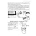
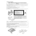
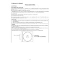
SAFETY PRECAUTION OF MD SECTION FOR SERVICE MANUAL
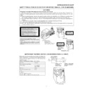
The AEL (ACCESSIBLE EMISSION LEVEL) of the laser power output is less than class 1 but the laser component is capable of emitting
radiation exceeding the limit for class 1. Therefore it is important that the following precautions are observer during servicing to protect your
eyes against exposure to the laser beam.
1) When the unit case cover is removed and LOADING SW (SW 1956) is turned on and then PLAY SW (SW 1954 mechanism PWB) is turned
on in a few second.
The laser will light for several second to detect a disk.
2) The laser power output of the pickup unit and replacement service parts are all factory pre-set before shipment.
Do not attempt to re-adjust the laser pickup unit during replacement or servicing.
3) Under no circumstances stare into the pickup lens at any time.
4) If laser optical unit becomes faulty, replace the complete laser optical unit.
5) CAUTION-USE of controls or adjustments, or performance of procedures other than those specified herein may result in hazardous
radiation exposure.
VARO !
Avattaessa ja suojalukitus ohitettaessa olet alttiina näkymättömälle lasersäteilylle. Älä katso säteeseen.
VARNING!
Osynlig laserstralning när denna del är öppnad och spärren är urkopplad. Betrakta ej strälen.
Precaution to be taken when replacing and servicing the laser pickup.
The following precautions must be observed during servicing to protect your eyesvagainst exposure to the laser.
Warning of possible eye damage when repairing:
If the AC power plug is connected when the inner cover of the unit is removed, the laser will light up during focus access (about
1 second) (Fig. 2-1).
During this operation, the laser will leak from the opening between the magnetic head and cartridge holder (Fig. 2-2).
In order to protect your eyes, you must not look at the laser during repair.
Before repairing, be sure to disconnect the AC power plug.
Figure 2-1
Figure 2-2
Magnetic Head
Optical Pickup
,,
Magnetic Head
Optical Pickup
Spindle Motor
Laser Beam
Cartridge Holder
Mechanism
Chassis
Chassis
Laser Diode Properties
●
Material: GaAlAs
●
Wavelength: 785 nm
●
Pulse time:
Read mode: 0.8 mW Continuous
Write mode: max 10 mW 0.5S
Read mode: 0.8 mW Continuous
Write mode: max 10 mW 0.5S
min cycle 1.5S
Repetition
Repetition
CAUTION - INVISIBLE LASER RADIATION WHEN OPEN AND INTERLOCKS DEFEATED
AVOID EXPOSURE TO BEAM .
AVOID EXPOSURE TO BEAM .
VARNING - OSYNLIG LASERSTR LNING N R DENNA DEL R …PPNAD OCH SP RRAR
R URKOPPLADE. STR LEN R FARLIG.
R URKOPPLADE. STR LEN R FARLIG.
ADVARSEL - USYNLIG LASERSTR LING N R DEKSEL PNES OG SIKKERHEDSL S
BRYTES. UNNG EKSPONERING FOR STR LEN.
BRYTES. UNNG EKSPONERING FOR STR LEN.
VARO! AVATTAESSA JA SUOJALUKITUS OHITETTAESSA OLET ALTTIINA
N KYM T…N LASERS TEILYLLE. L KATSO S TEESEN.
N KYM T…N LASERS TEILYLLE. L KATSO S TEESEN.
VARNING - OSYNLIG LASERSTR LING N R DENNA DEL R …PPNAD OCH SP RREN
R URKOPPLAD. BETRAKTA EJ STR LEN.
R URKOPPLAD. BETRAKTA EJ STR LEN.
ADVARSEL - USYNLIG LASERSTR LING VED BNING N R SIKKERHEDSAFBRYDERE
ER UDE AF FUNKTION. UNDG UDSETTELSE FOR STR LING.
ER UDE AF FUNKTION. UNDG UDSETTELSE FOR STR LING.
VAROITUS! LAITTEEN KÄYTTÄMINEN MUULLA KUIN TÄSSÄ KÄYTTÖOHJEESSA MAI
NITULLA TAVALLA SAATTAA ALTISTAA KÄYTTÄJÄN TURVALLISUUSLUOKAN 1
YLITTÄVÄLLE NÄKYMÄTTÖMÄLLE LASERSÄTEILYLLE.
NITULLA TAVALLA SAATTAA ALTISTAA KÄYTTÄJÄN TURVALLISUUSLUOKAN 1
YLITTÄVÄLLE NÄKYMÄTTÖMÄLLE LASERSÄTEILYLLE.
VARNING - OM APPARATEN ANVÄNDS PÅ ANNAT SÄTT ÄN I DENNA BRUKSANVISNI
NG SPECIFICERAS. KAN ANVÄNDAREN UTSÄTTAS FÖR OSYNLIG LASERSTRÅLNING,
SOM ÖVERSKRIDER GRÄNSEN FÖR LASERKLASS 1.
NG SPECIFICERAS. KAN ANVÄNDAREN UTSÄTTAS FÖR OSYNLIG LASERSTRÅLNING,
SOM ÖVERSKRIDER GRÄNSEN FÖR LASERKLASS 1.
WARNINGS
– 3 –
CD-MD3000H/CD-MD3000W
Precaution to be taken when replacing and servicing the Laser Pickup.
The AEL (Accessible Emission Level) of Laser Power Output for this model is specified to be lower than Class 1 Requirements.
However, the following precautions must be observed during servicing to protect your eyes against exposure to the Laser
beam.
(1) When the cabinet has been removed, the power is turned on without a compact disc, and the Pickup is on a position outer
than the lead-in position, the Laser will light for several seconds to detect a disc. Do not look into the Pickup Lens.
(2) The Laser Power Output of the Pickup inside the unit and replacement service parts have already been adjusted prior to
shipping.
(3) No adjustment to the Laser Power should be attempted when replacing or servicing the Pickup.
(4) Under no circumstances look directly into the Pickup Lens at any time.
(5) CAUTION - Use of controls or adjustments, or performance of procedures other than those specified herein may result in
(4) Under no circumstances look directly into the Pickup Lens at any time.
(5) CAUTION - Use of controls or adjustments, or performance of procedures other than those specified herein may result in
hazardous radiation exposure.
(For U.K.)
(Except for U.K.)
WARNINGS
SAFETY PRECAUTION OF CD SECTION FOR SERVICE MANUAL (FOR CD-MD3000H)
Laser Diode Properties
Material: GaAIAs
Wavelength: 780 nm
Emission Duration: continuous
Laser Output: max. 0.6 mW
Wavelength: 780 nm
Emission Duration: continuous
Laser Output: max. 0.6 mW
CAUTION-INVISIBLE LASER RADIATION WHEN OPEN. DO NOT STARE INTO
BEAM OR VIEW DIRECTLY WITH OPTICAL INSTRUMENTS.
BEAM OR VIEW DIRECTLY WITH OPTICAL INSTRUMENTS.
VARNING-OSYNLIG LASERSTRALNING NAR DENNA DEL AR OPPNAD. STIRRA
EJ IN I STRALEN OCH BETRAKTA EJ STRALEN MED OPTISKA INSTRUMENT.
EJ IN I STRALEN OCH BETRAKTA EJ STRALEN MED OPTISKA INSTRUMENT.
ADVERSEL-USYNLIG LASERSTRALING VED ABNING. SE IKKE IND I
STRALEN-HELLER IKKE MED OPTISKE INSTRUMENTER.
STRALEN-HELLER IKKE MED OPTISKE INSTRUMENTER.
VARO! AVATTAESSA OLET ALTTIINA NAKYMATON LASERSATEILYLLE.
ALA TUIJOTA SATEESEEN ALAKA KATSO SITA OPTISEN LAITTEEN LAPI.
ALA TUIJOTA SATEESEEN ALAKA KATSO SITA OPTISEN LAITTEEN LAPI.
VARNING-OSYNLIG LASERSTRALNING NAR DENNA DEL AR OPPNAD.
STIRRA EJ IN I STRALEN OCH BETRAKTA EJ STRALEN GENOM OPTISKT
INSTRUMENT.
ADVERSEL-USYNLIG LASERSTRALING NAR DEKSEL APNES. STIRR IKKE
INN I STRALEN ELLER SE DIREKTE MED OPTISKE INSTRUMENTER.
STIRRA EJ IN I STRALEN OCH BETRAKTA EJ STRALEN GENOM OPTISKT
INSTRUMENT.
ADVERSEL-USYNLIG LASERSTRALING NAR DEKSEL APNES. STIRR IKKE
INN I STRALEN ELLER SE DIREKTE MED OPTISKE INSTRUMENTER.
VAROITUS! LAITTEEN KÄYTTÄMINEN MUULLA KUIN TÄSSÄ
KÄYTTÖOHJEESSA MAINITULLA TAVALLA SAATTAA ALTISTAA
KÄYTTÄJÄN TURVALLISUUSLUOKAN 1 YLITTÄVÄLLE NÄKYMÄTTÖMÄLLE
LASERSÄTEILYLLE.
KÄYTTÖOHJEESSA MAINITULLA TAVALLA SAATTAA ALTISTAA
KÄYTTÄJÄN TURVALLISUUSLUOKAN 1 YLITTÄVÄLLE NÄKYMÄTTÖMÄLLE
LASERSÄTEILYLLE.
VARNING - OM APPARATEN ANVÄNDS PÅ ANNAT SÄTT ÄN I DENNA
BRUKSANVISNING SPECIFICERAS. KAN ANVÄNDAREN UTSÄTTAS FÖR
OSYNLIG LASERSTRÅLNING, SOM ÖVERSKRIDER GRÄNSEN FÖR
LASERKLASS 1.
BRUKSANVISNING SPECIFICERAS. KAN ANVÄNDAREN UTSÄTTAS FÖR
OSYNLIG LASERSTRÅLNING, SOM ÖVERSKRIDER GRÄNSEN FÖR
LASERKLASS 1.
IMPORTANT SERVICE NOTES (CD-MD3000H FOR U.K. ONLY)
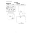
Before returning the unit to the customer after completion of a
repair or adjustment it is necessary for the following withstand
voltage test to be applied to ensure the unit is safe for the
customer to use.
Setting of Withstanding Voltage Tester and set.
repair or adjustment it is necessary for the following withstand
voltage test to be applied to ensure the unit is safe for the
customer to use.
Setting of Withstanding Voltage Tester and set.
Set name
set value
Withstanding Voltage Tester
Test voltage
4,240 VPEAK
3,000 VRMS
3,000 VRMS
Set time
6 secs
Set current (Cutoff current)
4 mA
Unit
Judgment
OK: The “GOOD” lamp lights.
NG: The “NG” lamp lights and the buzzer sounds.
NG: The “NG” lamp lights and the buzzer sounds.
PROBE
AC
OUT
UNIT
SHORT-CIRCUIT
AC POWER
SUPPLY CORD
AC POWER
SUPPLY CORD
CONNECT THE PROBE
TO GND OF CHASSIS
SCREW
TO GND OF CHASSIS
SCREW
WITHSTANDING
VOLTAGE TESTER
CHASSIS SCREW
CD-MD3000H/CD-MD3000W
– 4 –
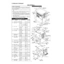
VOLTAGE SELECTION (FOR CD-MD3000W ONLY)
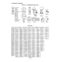
Before operating the unit on mains, check the preset voltage. If the voltage is different from your local voltage, adjust the voltage
as follows, Turn the selector with a screwdriver until the appropriate voltage number appears in the window (110 V, 127 V,
220 V or 230 V - 240 V AC).
as follows, Turn the selector with a screwdriver until the appropriate voltage number appears in the window (110 V, 127 V,
220 V or 230 V - 240 V AC).
QACCB0009AW00
Figure 4 AC POWER SUPPLY CORD AND PLUG ADAPTOR
QACCE0008AW00
QACCL0005AW00
Precaution to be taken when replacing and servicing the Laser Pickup.
The AEL (Accessible Emission Level) of Laser Power Output for this model is specified to be lower than Class 1 Requirements.
However, the following precautions must be observed during servicing to protect your eyes against exposure to the Laser
beam.
(1) When the cabinet has been removed, the power is turned on without a compact disc, and the Pickup is on a position outer
The AEL (Accessible Emission Level) of Laser Power Output for this model is specified to be lower than Class 1 Requirements.
However, the following precautions must be observed during servicing to protect your eyes against exposure to the Laser
beam.
(1) When the cabinet has been removed, the power is turned on without a compact disc, and the Pickup is on a position outer
than the lead-in position, the Laser will light for several seconds to detect a disc. Do not look into the Pickup Lens.
(2) The Laser Power Output of the Pickup inside the unit and replacement service parts have already been adjusted prior to
shipping.
(3) No adjustment to the Laser Power should be attempted when replacing or servicing the Pickup.
(4) Under no circumstances look directly into the Pickup Lens at any time.
(5) CAUTION - Use of controls or adjustments, or performance of procedures other than those specified herein may result in
(4) Under no circumstances look directly into the Pickup Lens at any time.
(5) CAUTION - Use of controls or adjustments, or performance of procedures other than those specified herein may result in
hazardous radiation exposure.
WARNINGS
SAFETY PRECAUTION OF CD SECTION FOR SERVICE MANUAL (FOR CD-MD3000W)
CAUTION
Laser Diode Properties
Material: GaAIAs
Wavelength: 780 nm
Emission Duration: continuous
Laser Output: max. 0.6 mW
Material: GaAIAs
Wavelength: 780 nm
Emission Duration: continuous
Laser Output: max. 0.6 mW
This Audio Tower System is classified as a CLASS 1 LA-
SER product.
SER product.
The CLASS 1 LASER PRODUCT label is located on the
rear cover.
rear cover.
Use of controls, adjustments or performance of proce-
dures other than those specified herein may result in haz-
ardous radiation exposure.
dures other than those specified herein may result in haz-
ardous radiation exposure.
As the laser beam used in this compact disc player is
harmful to the eyes, do not attempt to disassemble the
cabinet. Refer servicing to qualified personnel only.
harmful to the eyes, do not attempt to disassemble the
cabinet. Refer servicing to qualified personnel only.
CAUTION-INVISIBLE LASER RADIATION WHEN OPEN. DO NOT STARE INTO
BEAM OR VIEW DIRECTLY WITH OPTICAL INSTRUMENTS.
BEAM OR VIEW DIRECTLY WITH OPTICAL INSTRUMENTS.
VARNING-OSYNLIG LASERSTRALNING NAR DENNA DEL AR OPPNAD. STIRRA
EJ IN I STRALEN OCH BETRAKTA EJ STRALEN MED OPTISKA INSTRUMENT.
EJ IN I STRALEN OCH BETRAKTA EJ STRALEN MED OPTISKA INSTRUMENT.
ADVERSEL-USYNLIG LASERSTRALING VED ABNING. SE IKKE IND I
STRALEN-HELLER IKKE MED OPTISKE INSTRUMENTER.
STRALEN-HELLER IKKE MED OPTISKE INSTRUMENTER.
VARO! AVATTAESSA OLET ALTTIINA NAKYMATON LASERSATEILYLLE.
ALA TUIJOTA SATEESEEN ALAKA KATSO SITA OPTISEN LAITTEEN LAPI.
ALA TUIJOTA SATEESEEN ALAKA KATSO SITA OPTISEN LAITTEEN LAPI.
VARNING-OSYNLIG LASERSTRALNING NAR DENNA DEL AR OPPNAD.
STIRRA EJ IN I STRALEN OCH BETRAKTA EJ STRALEN GENOM OPTISKT
INSTRUMENT.
STIRRA EJ IN I STRALEN OCH BETRAKTA EJ STRALEN GENOM OPTISKT
INSTRUMENT.
ADVERSEL-USYNLIG LASERSTRALING NAR DEKSEL APNES. STIRR IKKE
INN I STRALEN ELLER SE DIREKTE MED OPTISKE INSTRUMENTER.
INN I STRALEN ELLER SE DIREKTE MED OPTISKE INSTRUMENTER.
QACCA0003AW00
QPLGA0004AWZZ
QPLGA0003AWZZ

