LG GR-S392QVC Service Manual ▷ View online
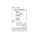
7-2-5 TEMPERATURE SENSOR CIRCUIT
The upper CIRCUIT reads REFRIGERATOR temperature and DEF-SENSOR temperature for defrosting into MICOM.
OPENING or SHORT state of each TEMPERATURE SENSOR are as follows.
OPENING or SHORT state of each TEMPERATURE SENSOR are as follows.
7-2-6 DOOR OPEN DETECTING CIRCUITS
- 22 -
SENSOR
CHECK POINT
NORMAL(-30 °C ~ 50 °C)
SHORT-CIRCUITED
OPEN
Refrigerator Sensor
POINT
Voltage
0.5 V ~ 4.5 V
0 V
5 V
Defrosting Sensor
POINT
Voltage
A
B
MEASURING POINTS
Freezer / Refrigerator Door
CLOSED
OPEN
IC1 (Pin No. 8)
5 V
0 V
- 23 -
7-2-7 TEMPERATURE COMPENSATION & OVERCOOLING/UNDERCOOLING COMPENSATION CIRCUIT
1. Refrigerator Temperature Compensation
➧
Table of Temperature Compensation by adjusting the resistance (Difference with the current temperature)
E.g.) If the refrigerator compensation resistance (RCR1) is changed from 10K (the current resistance) to 18K
(the adjustment resistance), the temperature of the refrigerator rises +1 °C.
Refrigerator
Resistance
Temperature Remark
(RCR1)
Compensation
180 K
Ω
+2.5 °C
Compensation by
56 K
Ω
+2.0 °C
raising the
33 K
Ω
+1.5°C
temperature
18 K
Ω
+1.0 °C
12 K
Ω
+0.5 °C
10 K
Ω
0 °C
Standard Temperature
8.2 K
Ω
-0.5°C
Compensation by
5.6 K
Ω
-1.0°C
lowering the
3.3 K
Ω
-1.5 °C
temperature
2 K
Ω
-2.0 °C
470
Ω
-2.5 °C
7-2-8 KEY BUTTON INPUT & DISPLAY LIGHT ON CIRCUIT
➧
The circuit shown above is to determine whether a function control key on the operation display is pushed and to turn on
the corresponding function indication LED. The drive type is the scan type.
the corresponding function indication LED. The drive type is the scan type.
- 24 -
7-5 MAIN PWB ASSEMBLY AND PARTS LIST
7-5-1 MAIN PWB ASSEMBLY
- 28 -
Click on the first or last page to see other GR-S392QVC service manuals if exist.

