|
|
WV-VF65B WV-RC36 WV-CA32A-14 WV-CA38 WV-LC10 WV-CC37 WV-CC38
Service Manual
|
80
|
8.41 MB
|

|
DMC-LC1PP DMC-LC1EB DMC-LC1EG DMC-LC1GC DMC-LC1GD DMC-LC1GN
DIGITAL CAMERA
Service Manual
|
|
4.33 MB
|
|
|
DMC-LC1PP DMC-LC1EB DMC-LC1EG DMC-LC1GC DMC-LC1GD DMC-LC1GN (serv.man2)
DIGITAL CAMERA
Service Manual
|
47
|
2.7 MB
|
|
|
PT-LC50U PT-LC50E PT-LC150
LCD PROJECTOR
Service Manual
|
127
|
15.76 MB
|

|
PT-LC70 PT-LC70U PT-LC70E PT-LC70 PT-LC170
LCD PROJECTOR
Service Manual
|
|
7.25 MB
|
|
|
AR-LC1 (serv.man2)
ARLC1 Service Manual
Service Manual
|
30
|
843.46 KB
|
|
|
MX-LC11
MXLC11 Service Manual
Service Manual
|
24
|
1.6 MB
|
|
|
MX-LC12 (serv.man2)
Updated March 2013
Service Manual
|
127
|
43.31 MB
|
|
|
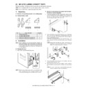
MX-LC12 (serv.man3)
MX-LC12 Installation Manual
Service Manual
|
7
|
1 MB
|
|
|
MX-LC13
Service Manual (Revised January 2016).
Service Manual
|
44
|
8.07 MB
|
|
|
MX-LC13 (serv.man2)
Service Manual (Revised July 2014).
Service Manual
|
43
|
8.61 MB
|
|
|
MX-LC17
Service Manual for N Version
Service Manual
|
23
|
6.22 MB
|
|
|
MX-LC10
Service Manual
Service Manual
|
30
|
1.82 MB
|
|
|
MX-LC12 (serv.man10)
Service Manual
Service Manual
|
21
|
1.94 MB
|
|
|
MX-LC13 (serv.man22)
Service Manual.
Service Manual
|
43
|
8.61 MB
|
|
|
MX-LC13N
Service Manual.
Service Manual
|
44
|
8.07 MB
|
|
|
MX-LC15
Service Manual
Service Manual
|
19
|
4.65 MB
|
|
|
MX-LC16
Service Manual
Service Manual
|
21
|
5.24 MB
|
|
|
32LV5700 (CHASSIS:LC12E)
Service Manual
|
120
|
10.89 MB
|
|
|
37LV5700 (CHASSIS:LC12E)
Service Manual
|
120
|
10.89 MB
|
|
|
42LV5700-CA (CHASSIS:LC12E)
Service Manual
|
120
|
10.89 MB
|
|
|
47LV5700-CA (CHASSIS:LC12E)
Service Manual
|
120
|
10.89 MB
|
|
|
55LV5700 (CHASSIS:LC12E)
Service Manual
|
48
|
12.07 MB
|
|
|
32LW5500-CA (CHASSIS:LC12C)
Service Manual
|
56
|
5.91 MB
|
|
|
42LW5500-CA (CHASSIS:LC12C)
Service Manual
|
56
|
5.91 MB
|
|
|
42LW6500-CA (CHASSIS:LC12C)
Service Manual
|
117
|
11.09 MB
|
|
|
47LW5500-CA (CHASSIS:LC12C)
Service Manual
|
56
|
5.91 MB
|
|
|
47LW6500-CA (CHASSIS:LC12C)
Service Manual
|
47
|
9.35 MB
|
|
|
47LW7200 (CHASSIS:LC12C)
Service Manual
|
47
|
9.89 MB
|
|
|
47LW9800-CA (CHASSIS:LC12D)
Service Manual
|
58
|
10.7 MB
|
|
|
55LW5500-CA (CHASSIS:LC12C)
Service Manual
|
56
|
7.78 MB
|
|
|
55LW6500-CA (CHASSIS:LC12C)
Service Manual
|
117
|
11.09 MB
|
|
|
55LW7200 (CHASSIS:LC12C)
Service Manual
|
47
|
9.89 MB
|
|
|
55LW9800-CA (CHASSIS:LC12D)
Service Manual
|
58
|
10.7 MB
|
|
|
72LZ9700-CA (CHASSIS:LC12C)
Service Manual
|
47
|
11.71 MB
|
|
|
72LZ9900-CA (CHASSIS:LC12N)
Service Manual
|
63
|
14.45 MB
|
|
|
65LW6500-CA (CHASSIS:LC12C)
Service Manual
|
117
|
6.08 MB
|
|
|
LC1
User Manual / Operation Manual
|
8
|
1.88 MB
|
|
|
LC1 (serv.man2)
User Manual / Operation Manual
|
8
|
5.75 MB
|
|
|
LC1 (serv.man3)
User Manual / Operation Manual
|
8
|
1.88 MB
|
|
|
LC1 (serv.man4)
User Manual / Operation Manual
|
8
|
1.89 MB
|
|
|
LC1 (serv.man5)
User Manual / Operation Manual
|
8
|
1.88 MB
|
|
|
LC1 (serv.man6)
User Manual / Operation Manual
|
8
|
1.89 MB
|
|
|
LC1 (serv.man7)
User Manual / Operation Manual
|
8
|
1.89 MB
|
|
|
LC1 (serv.man8)
User Manual / Operation Manual
|
8
|
1.89 MB
|
|
|
LC1 (serv.man9)
User Manual / Operation Manual
|
8
|
1.88 MB
|
|
|
LC1 (serv.man10)
User Manual / Operation Manual
|
8
|
1.88 MB
|
|
|
AR-LC1 (serv.man3)
ARLC1 Parts Guide
Service Manual / Parts Guide
|
17
|
1.33 MB
|
|
|
MX-LC11 (serv.man2)
Revised November 2011
Service Manual / Parts Guide
|
21
|
1.87 MB
|
|
|
MX-LC11 (serv.man3)
MXLC11 Complete Parts Guide
Service Manual / Parts Guide
|
20
|
1.78 MB
|
|
|
MX-LC12 (serv.man4)
July 2012
Service Manual / Parts Guide
|
19
|
2.49 MB
|
|
|
MX-LC13 (serv.man3)
MX-LC13N - MX-RB14 Complete Parts Guide - Revised January 2016
Service Manual / Parts Guide
|
75
|
27.63 MB
|
|
|
MX-LC13 (serv.man4)
MX-RB14 Complete Parts Guide - Revised June 2013
Service Manual / Parts Guide
|
64
|
9.89 MB
|
|
|
MX-LC17 (serv.man2)
Parts Guide for N Version
Service Manual / Parts Guide
|
27
|
7.22 MB
|
|
|
MX-LC17 (serv.man3)
Parts Guide (Revised June 2017).
Service Manual / Parts Guide
|
27
|
7.02 MB
|
|
|
MX-LC10 (serv.man2)
Parts Guide
Service Manual / Parts Guide
|
18
|
1.86 MB
|
|
|
MX-LC12 (serv.man11)
Parts Guide
Service Manual / Parts Guide
|
19
|
2.76 MB
|
|
|
MX-LC13 (serv.man23)
Parts Guide (Revised 2016).
Service Manual / Parts Guide
|
75
|
71.72 MB
|
|
|
MX-LC13N (serv.man2)
Parts Guide (Revised 2016).
Service Manual / Parts Guide
|
75
|
71.72 MB
|
|
|
MX-LC15 (serv.man2)
Parts Guide (Revised February 2015).
Service Manual / Parts Guide
|
19
|
4.84 MB
|
|
|
MX-LC16 (serv.man2)
Parts Guide (Revised February 2015).
Service Manual / Parts Guide
|
24
|
5.12 MB
|
|
|
AR-LC1
ARLC1 Specifications
Service Manual / Specification
|
1
|
845.25 KB
|
|
|
MX-LC12
All Sections
Service Manual / Specification
|
21
|
1.94 MB
|
|
|
AR-LC1 (serv.man4)
004-Correction to the AR-LC1N Parts Guide
Service Manual / Technical Bulletin
|
1
|
142.43 KB
|
|
|
AR-LC1 (serv.man5)
003-Correction to the AR-LC1n parts guide
Service Manual / Technical Bulletin
|
1
|
141.81 KB
|
|
|
AR-LC1 (serv.man6)
Supply of paper feeding roller rubbers as separate service packages. (WHITE)
Service Manual / Technical Bulletin
|
1
|
74.66 KB
|
|
|
AR-LC1 (serv.man7)
Addition Of Parts Carried Out As A Measure To Conform With Noise (EMI) Standards. (WHITE)
Service Manual / Technical Bulletin
|
4
|
173.09 KB
|
|
|
MX-LC11 (serv.man4)
CHANGE OF LCC MAIN PWB DUE TO TERMINATION OF PRODUCTION OF ZENER DIODE
Service Manual / Technical Bulletin
|
2
|
657.44 KB
|
|
|
MX-LC11 (serv.man5)
DISCONTINUATION OF PRODUCTION AND CHANGE OF LIFT MOTOR
Service Manual / Technical Bulletin
|
3
|
184.99 KB
|
|
|
MX-LC11 (serv.man6)
PRICE RANK SETUP FOR LCC HEATER KIT INDIVIDUAL PARTS
Service Manual / Technical Bulletin
|
1
|
158.31 KB
|
|
|
MX-LC12 (serv.man7)
UPGRADE OF PAPER FEED OPTION FINISHER DECURLER UNIT
Service Manual / Technical Bulletin
|
2
|
145.6 KB
|
|
|
MX-LC12 (serv.man8)
CHANGE OF LCC MAIN PWB DUE TO TERMINATION OF PRODUCTION OF ZENER DIODE
Service Manual / Technical Bulletin
|
2
|
657.44 KB
|
|
|
MX-LC12 (serv.man9)
DISCONTINUATION OF PRODUCTION AND CHANGE OF LIFT MOTOR
Service Manual / Technical Bulletin
|
3
|
184.99 KB
|
|
|
MX-LC13 (serv.man11)
UPGRADE OF PAPER FEED OPTION FINISHER DECURLER UNIT
Service Manual / Technical Bulletin
|
2
|
145.6 KB
|
|
|
MX-LC13 (serv.man12)
Enhancement of LC13 Main Drive Gear
Service Manual / Technical Bulletin
|
3
|
760.63 KB
|
|
|
MX-LC13 (serv.man13)
DISCONTINUATION OF PRODUCTION AND CHANGE OF LIFT MOTOR
Service Manual / Technical Bulletin
|
3
|
184.99 KB
|
|
|
MX-LC13 (serv.man14)
ENHANCEMENT OF PAPER GUIDE OPERABILITY WHEN USING SMALL SIZED PAPER
Service Manual / Technical Bulletin
|
2
|
86.49 KB
|
|
|
MX-LC13 (serv.man15)
IMPROVEMENTS FOR INSTALLING MX-LC13 N
Service Manual / Technical Bulletin
|
68
|
11.35 MB
|
|
|
MX-LC13 (serv.man16)
MODIFICATION OF NOISE GENERATED WHILE FEEDING THICK GLOSSY PAPER
Service Manual / Technical Bulletin
|
2
|
462.29 KB
|
|
|
MX-LC13 (serv.man17)
CCE-1293 COUNTERMEASURE FOR JAM (L1DF004_N ETC.) DUE TO THE CREASE(S) ON PAPER FEED BELT AT AIR PAPER UNIT SECTION
Service Manual / Technical Bulletin
|
5
|
485.98 KB
|
|
|
MX-LC13 (serv.man18)
FIRMWARE UPGRADE ... (3) Ver. 01.09.S1
Service Manual / Technical Bulletin
|
1
|
85.79 KB
|
|
|
MX-LC13 (serv.man19)
FIRMWARE UPGRADE ... (2)Ver 01.08.S1
Service Manual / Technical Bulletin
|
1
|
83.59 KB
|
|
|
MX-LC13 (serv.man20)
FIRMWARE UPGRADE FOR MXLC13 MXLCX3N
Service Manual / Technical Bulletin
|
1
|
85.78 KB
|
|
|
MX-LC13 (serv.man21)
ENHANCEMENT FOR PAPER FEED BELT DAMAGE OF AIR PAPER UNIT
Service Manual / Technical Bulletin
|
3
|
282.49 KB
|
|
|
MX-LC17 (serv.man4)
CCE 1799 SUPPLIED HARNESSES TO INSTALL OPTION (PERIPHERALS) N VERSION
Service Manual / Technical Bulletin
|
2
|
129.8 KB
|
|
|
MX-LC17 (serv.man5)
CCE 1708 ADDITION OF PAPER FEED BASE EDGE PROTECT SHEET
Service Manual / Technical Bulletin
|
2
|
134.34 KB
|
|
|
MX-LC17 (serv.man6)
CCE 1676 CHANGE DISUSE OF HARNESS FIXING BAND QTY CHANGE OF MINI CLAMP
Service Manual / Technical Bulletin
|
2
|
461.42 KB
|
|
|
MX-LC17 (serv.man7)
CCE 1655 REMOVAL OF LCC FIXING PLATE FROM PACKAGE
Service Manual / Technical Bulletin
|
1
|
139.37 KB
|
|
|
MX-LC10 (serv.man3)
DISCONTINUATION OF PRODUCTION AND CHANGE OF LIFT MOTOR
Service Manual / Technical Bulletin
|
3
|
184.99 KB
|
|
|
MX-LC12 (serv.man13)
DISCONTINUATION OF PRODUCTION AND CHANGE OF LIFT MOTOR
Service Manual / Technical Bulletin
|
3
|
184.99 KB
|
|
|
MX-LC13 (serv.man25)
Enhancement of LC13 Main Drive Gear
Service Manual / Technical Bulletin
|
3
|
760.63 KB
|
|
|
MX-LC13 (serv.man26)
DISCONTINUATION OF PRODUCTION AND CHANGE OF LIFT MOTOR
Service Manual / Technical Bulletin
|
3
|
184.99 KB
|
|
|
MX-LC13 (serv.man27)
IMPROVEMENTS FOR INSTALLING MX-LC13 N
Service Manual / Technical Bulletin
|
68
|
11.35 MB
|
|
|
MX-LC13 (serv.man28)
MODIFICATION OF NOISE GENERATED WHILE FEEDING THICK GLOSSY PAPER
Service Manual / Technical Bulletin
|
2
|
462.29 KB
|
|
|
MX-LC13 (serv.man29)
CCE-1293 COUNTERMEASURE FOR JAM (L1DF004_N ETC.) DUE TO THE CREASE(S) ON PAPER FEED BELT AT AIR PAPER UNIT SECTION
Service Manual / Technical Bulletin
|
5
|
485.98 KB
|
|
|
MX-LC13 (serv.man30)
Firmware Upgrade 2
Service Manual / Technical Bulletin
|
1
|
32.81 KB
|
|
|
MX-LC13 (serv.man31)
CCE-1106 Enhancement for paper feed belt damage of air feed unit.
Service Manual / Technical Bulletin
|
3
|
148.36 KB
|
|
|
MX-LC13N (serv.man3)
DISCONTINUATION OF PRODUCTION AND CHANGE OF LIFT MOTOR
Service Manual / Technical Bulletin
|
3
|
184.99 KB
|
|
|
MX-LC15 (serv.man3)
DISCONTINUATION OF PRODUCTION AND CHANGE OF LIFT MOTOR
Service Manual / Technical Bulletin
|
3
|
184.99 KB
|
|
|
MX-LC16 (serv.man3)
DISCONTINUATION OF PRODUCTION AND CHANGE OF LIFT MOTOR
Service Manual / Technical Bulletin
|
3
|
184.99 KB
|

|
MX-LC12 (serv.man5)
V 01.01.S1.00 - Bulletin Ref CCE-1745
Driver / Update
|
|
77.75 KB
|

|
MX-LC12 (serv.man6)
V 01.01.S1.00 - Bulletin Ref CCE-1745
Driver / Update
|
|
77.74 KB
|

|
MX-LC13 (serv.man5)
V 02.05.S1.00 - Bulletin Ref CCE-1745
Driver / Update
|
|
286.27 KB
|

|
MX-LC13 (serv.man6)
V 02.05.S1.00 - Bulletin Ref CCE-1745
Driver / Update
|
|
172.84 KB
|

|
MX-LC13 (serv.man7)
MX7500N)- Firmware Version 02.03.S1 - Refer to Bulletin CCE-1320
Driver / Update
|
|
302.78 KB
|

|
MX-LC13 (serv.man8)
MX7040N)- Firmware Version 02.03.S1 - Refer to Bulletin CCE-1320
Driver / Update
|
|
190.05 KB
|

|
MX-LC13 (serv.man9)
Firmware Version 01.09.S1 - Refer to Bulletin CCE-1143
Driver / Update
|
|
245.69 KB
|

|
MX-LC13 (serv.man10)
Firmware Version 01.08.S1 - Refer to Bulletin CCE-1121
Driver / Update
|
|
242.38 KB
|

|
MX-LC12 (serv.man12)
Special Firmware for LCC-ERR with MX-LC12 installed
Driver / Update
|
|
851.03 KB
|

|
MX-LC13 (serv.man24)
Firmware Upgrade 2
Driver / Update
|
|
167.82 KB
|

