JBL ES 150P (serv.man3) Service Manual ▷ View online
Service Manual
Released EU2008
Harman/kardon, Inc.
Rev 1, 6/2011
250 Crossways Park Dr.
Woodbury, New York, 11797
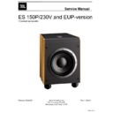
ES 150P/230V and EUP-version
Powered subwoofer
Page 1 of 41
- CONTENTS -
BASIC SPECIFICATIONS …………….……..…………..2
DETAILED SPECIFICATIONS ……….……..…………..3
PARTS LIST....……………………………….….….…......5
TEST SET-UP AND PROCEDURE......……..…...…..…6
EXPLODED VIEW/PARTS LIST…….….….…………....7
SCHEMATICS................................….….……………....9
P.C.B. DRAWINGS….…………………………………...10-30
ES150P SPECIFICATIONS
Amplifier Power (RMS):
300 Watts
Peak Dynamic Power *:
500 Watts
Driver:
10"
(254mm) PolyPlas™
Inputs:
Line Level (switchable to LFE)
Low-Pass Frequency:
Variable from 50Hz to 150Hz
(24dB/octave, continuously variable)
(24dB/octave, continuously variable)
Frequency Response:
27Hz – Low-pass crossover setting
Dimensions (H x W x D):
18" x 13-1/4" x 15-1/4" (457mm x 337mm x 387mm)
Weight:
39
lb/17.7kg
JBL continually strives to update and improve existing products, as well as create new ones. The
specifications and details in this and related JBL publications are therefore subject to change without notice.
*
The Peak Dynamic Power is measured by recording the highest center-to-peak voltage measured across the output of a resistive load equal to
minimum impedance of the transducer, using a 50Hz sine wave burst, 3 cycles on, 17 cycles off.
ES150P
JBL
ES 150P/230V and EUP Service Manual
Page 2 of 41
Pages 31-41 are added schematics for the EUP-version.
JBL ES150P 225W Powered Sub Amp
LINE VOLTAGE
Yes/No
Hi/Lo Line
Nom.
Unit
Notes
US 120vac/60Hz
Yes
108-132
120
Vrms
Normal Operation
EU 230vac/50-60Hz
Yes
207-253
230
Vrms
Normal operation, MOMS required
Parameter
Specification
Unit
QA Test
Limits
Conditions
Notes
Amp Section
Type (Class AB, D, other)
Type (Class AB, D, other)
D
n/a
n/a
Min. Load Impedance (speaker)
4
Ohms
n/a
Nominal
AVG System impedance
5.18
Ohms
Reference
AP Computed based on system
impedance curve
Over the BW of 20 to 500Hz
Rated Output Power
225
Watts
210
AVG RMS Dynamic Power
245
Watts
240
Average RMS power, 3/20 Cycles 50 Hz,
Driven 6dB above its input sensitivity ,
average of the first 4 consecutive peaks
THD @ Rated Power
0.5
%
1
22k filter
THD @ 1 Watt
0.2
%
0.3
22k filter
DC Offset
10
mV-DC
30
@ Speaker Outputs
Damping factor
>50
DF
20
Measured at amplifier board
Measured at the speaker cable. 189 Watts
@ THD < 0.1 % @ 50 Hz
Input Sensitivity
Input Frequency
Input Frequency
50
Hz
50
Nominal Freq.
L or R Inputs
11
mVrms
±1dB
To 1 Watt
Single input driven
LFE mode using L or R inputs
11
mVrms
±1dB
To 1 Watt
Single input driven, LFE switch ON
System Gain
45
dB
Reference
Single input driven Normal or LFE mode
Signal to Noise
SNR-A-Weighted
SNR-A-Weighted
80
dBA
75
relative to 1W
A-Weighting filter
SNR-unweighted
65
dBr
60
relative to 1W
22K filter
Residual Noise Floor
<2.0 mVrms(max)
2.5
Volume @max, w/ A/P Swept
Bandpass Measurement (Line
freq.+ harmonics) (BW=20 KHz)
Line level inputs must be terminated using
1KOHM
Input Impedance
Line Input (L, R,LFE)
Line Input (L, R,LFE)
10K
ohms
n/a
Nominal
Filters
LP filter Variable
LP filter Variable
50-150
Hz
± 10
4th Order variable-24 db/Octave
Subsonic filter (HPF) 2nd Order
Fixed
Friend circuit
Fixed
LFE Low pass
200>LP<500
Hz
LFE input driven only
Limiter
THD at Max. Output Power
13
%
functional
Drive unit 6dB above the required
level to obtain full power
Approximately 208mV
Maximum THD as a result of limiting.
Features
--
Volume pot Taper (lin/log)
LOG
--
functional
A Taper
Phase switch
0-180
deg
functional
LP Filter defeat switch
YES
functional
Disables LP filter, intended for LFE
LED indicator
YES
functional
Bicolor LED located in top of the cabinet,
RED-Standby, GRN-Active
Input Configuration
Line In (L,R) & LFE
YES
--
functional
Dual RCA jack, for LFE use either L or R inputs
Signal Sensing (ATO)
Auto-Turn-On (yes/no)
Auto-Turn-On (yes/no)
YES
functional
ATO Input test frequency
50
Hz
functional
ATO Level LFE Input
2
mV
functional
Maximum acceptable level.
ATO Turn-on time
5
ms
functional
Amp connected and AC on, then
input signal applied
Auto Mute/ Turn-OFF Time
5-15
minutes
5-15
T before muting, after signal is
removed
Auto turn of time (T) must be 5 > T < 15
Minutes
Power on Delay time
3
sec.
4
After AC Power is applied
ES150P
JBL
ES 150P/230V and EUP Service Manual
Page 3 of 41
Parameter
Specification
Unit
QA Test
Limits
Conditions
Notes
Transients/Pops
ATO Transient
0.5
V-peak
0.5V
@ Speaker Output
Amplifier activated by signal presence at the
Line input
Turn-on Transient
0.5
V-peak
0.8V
@ Speaker Output
AC Line cycled from OFF to ON
Turn-off Transient
0.5
V-peak
0.8V
@ Speaker Output
AC Line cycled from ON to OFF
Efficiency
Efficiency
61
%
60
Test conducted at rated power
250W
Nominal Line voltage
Efficiency at 1/8 of rated power
45
%
42
Test conducted at 31.25 WRMS
Nominal Line voltage-Rated impedance 4
Ohms
Off state input power
12
Watts
14
Nominal Line voltage RED LED
Stand-by Input Power
18
Watts
18
@ nom. line voltage
Maximum allowable input power under
nominal Input voltage and frequency, HOT
or COLD operation. LED GREEN no signal
applied
Power Cons. @ rated power
367
Watts
375
@ nom. line voltage
225 Watts @ 4 Ohms nominal line voltage
Protections
Short Circuit Protection
YES
functional Direct short at output
Amplifier should resume operation after
short circuit condition removal
Thermal Protection
YES
functional
@1/8 max unclipped Power at
1.06 times the input voltage
Temperature rise in accessible metal parts
should not exceed 35K rise for domestic
(refer to requirements sheet).
DC Offset Protection
YES
-
DC present at Speaker Out leads
Design must insure no Offset at the speaker
output under any operating condition
including abnormal operation
Line Fuse Rating
USA-Domestic
3.15
Amps
3.15
Type-T or Slo Blo-250 V
EU
2
Amps
2
Type-T or Slo Blo-250 V, Low
Breaking capacity
Other Parameters/Notes:
1. Limiter circuit response must be clean sounding with no apparent pops, noises, or pumping.
1. Limiter circuit response must be clean sounding with no apparent pops, noises, or pumping.
2. Plate dimensions not to exceed 11.81"H x 7.87"W and the plate must be airtight with no possibility of air leaks (plastic cover required).
3. Volume control should be at the input buffer stage in order to lessen the possibility of clipping the input section with highly dynamic audio material.
4. ALL SPECS SHOULD BE MEASURED AT NOMINAL LINE VOLTAGE.
ES150P
JBL
ES 150P/230V and EUP Service Manual
Page 4 of 41

