JBL E 150P (serv.man13) User Manual / Operation Manual ▷ View online
English
DIGITAL RECEIVER/PROCESSOR –
LFE CONNECTION
LFE CONNECTION
Use this installation method for
Dolby Digital, DTS
Dolby Digital, DTS
®
or other digi-
tal surround processors that
have bass-management
programming, or for analog
receivers/processors that have
a filtered subwoofer output:
have bass-management
programming, or for analog
receivers/processors that have
a filtered subwoofer output:
IMPORTANT: Make sure that the
LFE toggle switch on the sub-
woofer is in the “LFE” position.
Use the line-level input jacks for
the Low-Frequency Effects
channel. Connect these jacks to
the LFE output or subwoofer
output on your receiver or
amplifier.
LFE toggle switch on the sub-
woofer is in the “LFE” position.
Use the line-level input jacks for
the Low-Frequency Effects
channel. Connect these jacks to
the LFE output or subwoofer
output on your receiver or
amplifier.
Note: If your receiver or ampli-
fier has only one subwoofer out-
put jack, then you may connect
the subwoofer output on your
receiver/preamplifier to either
the left or right line-level input
on the subwoofer. It makes no
difference which jack you
choose.
fier has only one subwoofer out-
put jack, then you may connect
the subwoofer output on your
receiver/preamplifier to either
the left or right line-level input
on the subwoofer. It makes no
difference which jack you
choose.
Connect each speaker to the
corresponding speaker termi-
nals on your receiver or ampli-
fier.
corresponding speaker termi-
nals on your receiver or ampli-
fier.
Make sure that you have config-
ured your surround-sound
processor for “Subwoofer On”
ured your surround-sound
processor for “Subwoofer On”
or “LFE On.” The front left, front
right, center and rear speakers
should be set to “Small” or
“Large” depending on their size
and frequency response.
Consult your receiver’s or
processor’s owner’s manual.
right, center and rear speakers
should be set to “Small” or
“Large” depending on their size
and frequency response.
Consult your receiver’s or
processor’s owner’s manual.
CROSSOVER
FREQUENCY
FREQUENCY
LEVEL
LINE LEVEL IN
PHASE
Min
Max
L R
LFE NORMAL
HIGH
LEVEL
IN
L
R
HIGH
LEVEL
OUT
+ –
50Hz
0º
180º
150Hz
Subwoofer
Output/LFE
RECEIVER/PREAMPLIFIER
L
R
For LFE use L or R
English
OPERATION
When the unit is plugged in and
the power switch is on and no
signal is received, the LEDs on
the front of the unit will turn red.
When a signal is present, the
LEDs will turn green.
the power switch is on and no
signal is received, the LEDs on
the front of the unit will turn red.
When a signal is present, the
LEDs will turn green.
Note: It will take several min-
utes for the LEDs to turn from
utes for the LEDs to turn from
green to red after the input sig-
nal to the subwoofer is
removed. Due to JBL’s unique,
high-output, high-efficiency
amplifier design, power con-
sumption is minimal when the
subwoofer is not receiving a
signal. Of course, the subwoofer
can be turned off, whenever
nal to the subwoofer is
removed. Due to JBL’s unique,
high-output, high-efficiency
amplifier design, power con-
sumption is minimal when the
subwoofer is not receiving a
signal. Of course, the subwoofer
can be turned off, whenever
desired, if you do not wish
to leave it in auto (standby)
mode.
to leave it in auto (standby)
mode.
The subwoofer Level Control
adjusts the volume of the
subwoofer relative to the rest of
the system. Proper level adjust-
ment depends on several vari-
ables such as room size, sub-
adjusts the volume of the
subwoofer relative to the rest of
the system. Proper level adjust-
ment depends on several vari-
ables such as room size, sub-
woofer placement, type of main
speakers and listener position.
Adjust the subwoofer level so
that the volume of the bass
information is pleasing to you.
speakers and listener position.
Adjust the subwoofer level so
that the volume of the bass
information is pleasing to you.
CROSSOVER ADJUSTMENTS
The Crossover Frequency
Control determines the highest
frequency at which the sub-
woofer reproduces sounds. If
your main speakers can com-
fortably reproduce some low-
frequency sounds, set this con-
trol to a lower frequency setting,
between 50Hz – 100Hz. This will
concentrate the subwoofer’s
efforts on the ultradeep bass
sounds required by today’s films
and music. If you are using
smaller bookshelf speakers that
do not extend to the lower bass
frequencies, set the low-pass
crossover control to a higher
setting, between 120Hz – 150Hz.
This control is not used when
the LFE switch is in the “LFE”
position.
the LFE switch is in the “LFE”
position.
CAUTION
RISK OF ELECTRIC SHOCK
DO NOT OPEN
CROSSOVER
FREQUENCY
FREQUENCY
LEVEL
LINE LEVEL IN
PHASE
Min
Max
L
R
L R
For LFE use L or R
LFE NORMAL
HIGH
LEVEL
IN
L
R
HIGH
LEVEL
OUT
+ –
50Hz
0º
180º
150Hz
POWER
ON
OFF
LEVEL CONTROL
POWER
English
TROUBLESHOOTING
If you used the high-level
(speaker) inputs and there is no
sound from any of the speakers:
(speaker) inputs and there is no
sound from any of the speakers:
• Check that receiver/amplifier
is on and a source is playing.
is on and a source is playing.
• Check that powered
subwoofer is plugged into
an active electrical outlet
and is switched on.
subwoofer is plugged into
an active electrical outlet
and is switched on.
• Check all wires and connec-
tions between receiver/
amplifier and speakers. Make
sure all wires are connected.
Make sure none of the speaker
wires are frayed, cut or
punctured.
tions between receiver/
amplifier and speakers. Make
sure all wires are connected.
Make sure none of the speaker
wires are frayed, cut or
punctured.
• Review proper operation
of your receiver/amplifier.
of your receiver/amplifier.
If there is low (or no) bass
output:
output:
• Make sure the connections to
the left and right “Speaker
Inputs” have the correct
polarity (+ and –).
the left and right “Speaker
Inputs” have the correct
polarity (+ and –).
• Make sure that the subwoofer
is plugged into an active elec-
trical outlet and switched on.
is plugged into an active elec-
trical outlet and switched on.
• Adjust the crossover point.
• Flip the Phase Control switch
to the opposite position.
to the opposite position.
• If you are using a Dolby
Digital/DTS receiver or
processor, make sure that the
subwoofer adjustments on
the receiver/processor are
set up correctly.
Digital/DTS receiver or
processor, make sure that the
subwoofer adjustments on
the receiver/processor are
set up correctly.
• Slowly turn the Level
Control clockwise until you
begin to hear the desired
amount of bass.
Control clockwise until you
begin to hear the desired
amount of bass.
If you used the line-level inputs
and there is no sound from the
subwoofer:
and there is no sound from the
subwoofer:
• Check that receiver/amplifier
is on and a source is playing.
is on and a source is playing.
• Check that powered sub-
woofer is plugged into an active
electrical outlet and is switched
on.
woofer is plugged into an active
electrical outlet and is switched
on.
• Check all wires and con-
nections between receiver/
amplifier and subwoofer. Make
sure all wires are connected.
Make sure none of the wires
are frayed, cut or punctured.
nections between receiver/
amplifier and subwoofer. Make
sure all wires are connected.
Make sure none of the wires
are frayed, cut or punctured.
• Review proper operation of
your receiver/amplifier.
your receiver/amplifier.
• Slowly turn the Level
Control clockwise until you
begin to hear the desired
amount of bass.
Control clockwise until you
begin to hear the desired
amount of bass.
• Make sure that you have con-
figured your receiver/processor
so that the subwoofer/LFE out-
put is on.
figured your receiver/processor
so that the subwoofer/LFE out-
put is on.
PHASE CONTROL
The Phase Control determines
whether the subwoofer’s pis-
ton-like action moves in and out
in phase with the main speak-
ers or opposite the main speak-
ers. There is no correct or
incorrect setting. Proper phase
adjustment depends on several
variables such as subwoofer
placement and listener position.
Adjust the phase switch to
maximize bass output at the lis-
tening position.
Remember, every system, room
and listener is different. There
are no right or wrong settings;
this switch offers the added
flexibility to adjust your sub-
woofer for optimum perform-
ance for your specific listening
conditions without having to
move your speakers. If at some
time in the future you happen to
rearrange your listening room
and move your speakers, you
should experiment with the
phase switch in both positions,
and leave it in the position that
maximizes bass performance.
and leave it in the position that
maximizes bass performance.
English
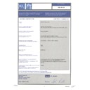
Declaration of Conformity
We, Harman Consumer International
2, route de Tours
72500 Chateau-du-Loir
France
72500 Chateau-du-Loir
France
declare in own responsibility, that the products described in
this owner’s manual are in compliance with technical stan-
dards:
this owner’s manual are in compliance with technical stan-
dards:
EN 60065:1998
EN 55013:A14/1999
EN 55020/A14:1999
EN 61000-3-2/A14:1999
EN 61000-3-3/1.1995
EN 55013:A14/1999
EN 55020/A14:1999
EN 61000-3-2/A14:1999
EN 61000-3-3/1.1995
Gary Mardell
Harman Consumer International
Chateau-du-Loir, France 2/03
© 2003 Harman International Industries, Incorporated
JBL is a registered trademark of Harman International Industries, Incorporated.
Part No.351248-001
PRO SOUND COMES HOME
™
JBL Consumer Products, 250 Crossways Park Drive, Woodbury, NY 11797
2, route de Tours, 72500 Chateau-du-Loir, France
800.336.4JBL (4525) (USA only) www.jbl.com
* Trademark of Dolby Laboratories.
DTS is a registered trademark of Digital Theater Systems, Inc.
All features and specifications are subject to change
without notice.
without notice.
All dimensions include grilles and feet.
SPECIFICATIONS
E150P
E250P
Amplifier
Power (RMS):
150 Watts
250 Watts
Driver:
250mm (10") PolyPlas™
300mm (12") PolyPlas™
Inputs:
Line Level (switchable to LFE)
Line Level (switchable to LFE)
and Speaker Level with
and Speaker Level with
5-way binding posts
5-way binding posts
Outputs:
Speaker Level, High-Pass with
Speaker Level, High-Pass with
5-way binding posts
5-way binding posts
Low-Pass
Frequency:
Continuously variable
Continuously variable
from 50Hz – 150Hz
from 50Hz – 150Hz
High-Pass
Frequency:
150Hz when using
150Hz when using
speaker-level output
speaker-level outputs
Frequency
Response:
27Hz – low-pass
25Hz – low-pass
crossover setting
crossover setting
Dimensions
(H x W x D):
(H x W x D):
450mm x 309mm x 384mm
500mm x 365mm x 435mm
Weight:
15.5kg
20.1kg
Display

