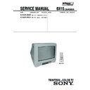
Sony KV-BM14N40 Service Manual ▷ View online
– 52 –
KV-BM14N40/BM14N70
RM-W151
BA033T
SE135N-LF38
4-6.
SEMICONDUCTORS
DIODE
BY228/A52A
CATHODE
ANODE
CATHODE
ANODE
(GRN)
ANODE
(GRN)
CATHODE
ANODE
CATHODE
ANODE
SPB-25MVWF
D3SB60F3
HSS82-TJ
MTZJ-T-77-15
RD5.1ESB2
UPC574J
1SS133T-77
MTZJ-T-77-15
RD5.1ESB2
UPC574J
1SS133T-77
10ERB20-TA2B5
10ERB20-TB3
11EQS10-TB5
AMO1AV1
D1NL20U
D3S6M-F
EGP20G
EL1Z
GP08D
RU4AM-T3
S3L20UF4
10ERB20-TB3
11EQS10-TB5
AMO1AV1
D1NL20U
D3S6M-F
EGP20G
EL1Z
GP08D
RU4AM-T3
S3L20UF4
UDZSTE-175.6B
UDZSTE-179.1B
MA2ZD140001S0
UDZSTE-179.1B
MA2ZD140001S0
ANODE
CATHODE
MMDL914T1
RD3.3SB
RD3.6SB
RD3.3SB
RD3.6SB
TRANSISTOR
1PS226-115
2SC3209LK
IRF614-037
TJM4558CDT
LM2903DT
CAT24WC16J1-TE1
LM2903DT
CAT24WC16J1-TE1
STV9302A
IC
E C B
1
7
3
1
2
1
3
2
MSB709-RT1
MSD601-RT1
UN2211
UN2216
MSD601-RT1
UN2211
UN2216
2SA1091-0
2SC3779C
2SC3779C
FN155
E
B
C
RPM7240-SH5
TA7805S
2SC5885
Small Outline L-leaded Package
Pin 8~98
Pin 8~98
SOP
1
TOP VIEW
TOP VIEW
TDA11010H
TDA11001H/
N1A000AE
TDA11001H/
N1A000AE
AN17804A
– 53 –
KV-BM14N40/BM14N70
RM-W151
STR-F6267SLF1357
IC
TDA6108AJF/N1
1
9
BA18BC0FP-E2
PQ018EFO1SZH
PQ09RD1SJ00H
PQ018EFO1SZH
PQ09RD1SJ00H
– 54 –
KV-BM14N40/BM14N70
RM-W151
•
Items marked "
∗ " are not stocked since
they are seldom required for routine
ser vice. Some delay should be
anticipated when ordering these items.
ser vice. Some delay should be
anticipated when ordering these items.
The components identified by
shading and mark
shading and mark
! are critical
for safety.
Replace only with part number
specified.
Replace only with part number
specified.
NOTE:
• Items with no part number and no
description are not stocked because
they are seldom required for routine
service.
they are seldom required for routine
service.
• The construction parts of an assembled
par t are indicated with a collation
number in the remark column.
number in the remark column.
5-1.
CHASSIS
r : 7-685-648-79
SCREW +BVTP 3
× 12 TYPE2 IT-3
p : 7-685-663-71
SCREW +BVTP 4
× 16 TYPE2 IT-3
12
5
27
4
3
25
1
26
13
8
8
9
10
11
14
15
6
24
17
13
16
18
20
22
21
19
7
2
23
SECTION 5
EXPLODED VIEWS
– 55 –
KV-BM14N40/BM14N70
RM-W151
1
X-4042-355-1
BEZNET ASSY
3,4
26,27
26,27
2
4-093-582-01
DOOR CONTROL
3
4-092-230-01
BUTTON POWER
4
4-036-405-11
SPRING COMPRESSION
5
! 8-735-570-05
PICTURE TUBE (A34LRG70X)
6
1-452-032-00
MAGNET DISC
7
4-094-153-01
REAR COVER (x 6 SCREWS)
8
4-081-577-01
SPACER(S) DY
9
4-077-228-02
PIECE TLH CONVERGENCE
10
! 8-451-401-41
DEFLECTION YOKE (Y14RSA-S3)
11
* A-1410-149-A MOUNTED PWB, (VAR), C
12
3-704-372-11
HOLDER HV CABLE
13
4-057-862-01
SCREW, TAPPING 5+ CROWN WASHER
14
4-095-706-01
SPRING EXTENSION
15
1-456-278-11
DEGAUSSING COIL (KV-BM14N40)
1-456-277-11
DEGAUSSING COIL (KV-BM14N70)
16
4-094-690-01
PIECE A(90) CONV CORRECT
17
1-825-293-11
LOUD SPEAKER (5 x 9 CM)
REF. NO. PART NO.
DESCRIPTION
REMARK
REF. NO. PART NO.
DESCRIPTION
REMARK
18
* A-1302-613-A COMPLETE PWB, A
(KV-BM14N40)
* A-1302-625-A COMPLETE PWB, A
(KV-BM14N70)
19
! 1-453-309-21
TRANSFORMER ASSY FLYBACK
(NX-4450//M3A4)
20
8-598-620-10
TUNER FSS BTP-AA402
21
4-093-758-51
BRACKET TERMINAL
(x 2 SCREWS)
22
! 1-575-023-11
CORD POWER (WITH CONNECTOR)
(KV-BM14N40)
! 1-827-949-11
AC POWER CORD (WITH CONNECTOR)
(KV-BM14N70)
23
4-022-115-00
HOLDER AC CORD
24
4-092-370-01
BRACKET FBT (z ONE SCREW)
25
1-477-678-21
TOP SWITCH BLOCK
26
* 4-093-771-01
COVER, FRONT PANEL
27
* 4-092-231-01
GUIDE LIGHT
Click on the first or last page to see other KV-BM14N40 service manuals if exist.

