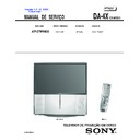
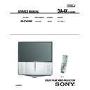
Sony KP-57WV600 Service Manual ▷ View online
TELEVISOR DE PROJEÇÃO EM CORES
MANUAL DE SERVIÇO
DA-4X
CHASSIS
MODEL NAME
REMOTE COMMANDER
DESTINATION
CHASSIS NO.
9-888-008-01
KP-57WV600
RM-Y188
BRAZIL
SCC-P92DA
Self Diagnosis
Supported model
KP-57WV600
RM-Y188
Versão 1.3 12. 2004
Clique aqui
— 3 —
KP-57WV600
TABLE OF CONTENTS
Specifications...................................................................... 4
Warnings and Cautions.......................................................5
Safety Check-Out ...............................................................6
Self-Diagnostic Function.....................................................7
1. DISASSEMBLY
1-1. Rear Board Removal ........................................................10
1-2. Chassis Assembly Removal ............................................. 10
1-3. Service Position................................................................ 10
1-4. Terminal Board.................................................................. 11
1-5. AD Board, B Board, MB Board, BM1C Board,
and U Board Removal ...................................................... 11
1-6. D Board, A Board, and G Board Remvoal ........................ 12
1-7. High-Voltage Cable Installation and Removal .................. 12
1-8. Picture Tube Removal ......................................................13
1-9. Grille, HA Board, HM Board, and HB Board Removal...... 13
1-10. Beznet Assembly Removal............................................... 14
1-11. SR Board Removal...........................................................14
1-12. Mirror Cover Removal ......................................................15
2. SET-UP ADJUSTMENTS
2-1. Screen Voltage Adjustment (G2) (Coarse Adjustment)..... 16
2-2. Screen (G2) Adjustment (Fine Adjustments) .................... 16
2-3. Deflection Yoke Tilt Adjustment......................................... 16
2-4. Focus Lens Adjustment ....................................................17
2-5. Focus VR Adjustment .......................................................17
2-6. 2-Pole Magnet Adjustment................................................ 18
2-7. Centering Magnet Adjustment ......................................... 18
2-8. 4-Pole Magnet Adjustment................................................ 18
2-9. Defocus Adjustment (Blue) ............................................... 18
2-10. Electrical Adjustments By Remote Commander............... 19
2-11. Service Data Lists.............................................................20
2-12. Registration Adjustment (PJE mode only) ........................ 48
2-13. PJE Adjustment (Sub Deflection Adjustment)................... 50
2-14. Auto Registration Offsets..................................................53
2-15. Auto Registration Error Codes.......................................... 54
2-16. Auto Registration Diagnostics........................................... 55
3. SAFETY RELATED ADJUSTMENTS
D BOARD
3-1. HV Regulation Circuit Check and Adjustment .................. 56
3-2. HV Hold Down Circuit Operation
Check and Adjustment......................................................56
G BOARD
3-3. +B Max Voltage Confirmation ........................................... 57
3-4. +B OVP Confirmation .......................................................57
4. CIRCUIT ADJUSTMENTS
4-1. P&P Sub Contrast Adjustment (Video) (SCON)................ 58
4-2. P&P Sub Contrast Adjustment (RF) (SCON).................... 58
4-3. P&P Sub-Hue and Sub-Color Adjustment Video
(SHUE, SCOL).................................................................. 58
4-4. P&P Sub-Hue and Sub-Color Adjustment (RF)
(SHUE, SCOL).................................................................. 58
4-5. Blue Offset Adjustment .....................................................59
5. DIAGRAMS
5-1. Circuit Boards Location.....................................................60
5-2. Printed Wiring Boards and
Schematic Diagrams Information...................................... 60
5-3. Block Diagrams................................................................. 62
5-4. Schematics and Supporting Information........................... 65
VM Board..................................................................... 65
CR Board..................................................................... 67
CG Board..................................................................... 68
CB Board..................................................................... 69
U Board ....................................................................... 70
A Board........................................................................ 72
B Board ....................................................................... 75
MS1 Board .................................................................. 83
G Board ....................................................................... 86
AD Board ..................................................................... 88
D Board ....................................................................... 91
MB Board..................................................................... 94
HB Board................................................................... 100
HM Board .................................................................. 101
SR Board................................................................... 102
HA Board ................................................................... 103
5-5. Semiconductors..............................................................104
6. EXPLODED VIEWS
6-1. Cover .............................................................................. 105
6-2. Chassis........................................................................... 106
6-3. Picture Tube ................................................................... 107
7. ELECTRICAL PARTS LIST..........................................................108
SECTION TITLE
PAGE
SECTION TITLE
PAGE
4
Outr
as
Informações
SETUP
W
e
lcome
SET
U
P
SETUP
SETUP
Especificações Técnicas
Projeto e especificações sujeitos a alterações sem prévia comunicação.
Acessórios Opcionais (não fornecidos)
❑
Cabo A/V
❑
Cabo de Áudio
❑
Cabo Vídeo Componente
❑
Cabo Control S
❑
Memory Stick: 16 MB (MSA-16A); 32 MB (MSA-32A);
64 MB (MSA-64A); 128 MB (MSA-128A)
64 MB (MSA-64A); 128 MB (MSA-128A)
Sistema de Projeção
3 tubos de imagem, 3 lentes, sistema horizontal em linha
Tudo de Imagem
Tubos monocromáticos de 7 polegadas de alto brilho (6,3 polegadas de área),
com sistema de resfriamento líquido e acoplamento óptico
com sistema de resfriamento líquido e acoplamento óptico
Lentes de Projeção
Alta performance, lentes F1,1 híbridas de diâmetro grande
Antena
Terminal externo de 75 ohm para VHF/UHF
Sistema de televisão
PAL-M, NTSC
Cobertura de canais
VHF
2-13
UHF
14-69
CATV
1-125
Alimentação
110~220V CA, 50/60 Hz
Entradas/Saídas
Vídeo (IN)
4 total (1 no painel frontal)
S Video (IN)
3 total (1 no painel frontal)
Áudio (IN)
6 total (1 no painel frontal)
Vídeo Componente
2 (Y, P
B
, P
R
)
TO CONVERTER
1
MEMORY STICK
1
RF
1
AUX
1
CONTROL S (IN/OUT)
1
MONITOR OUT
1
Áudio Fixo/Variável (OUT)
1
Acessórios Fornecidos
Controle Remoto
RM-Y188
Pilhas do tipo AA (R6)
2 para o controle remoto
Memory Stick (demonstração)
Tamanho da Tela 57”
Diagonal Visual Aproximada:
144 cm
Potência de Áudio (W RMS) a 1 kHz,
500 m Vrms, 10% THD
500 m Vrms, 10% THD
20W x 2
Dimensões (L x A x P)
1361 x 1394 x 689 mm
Peso
96,5 Kg
Consumo máximo de energia
Em uso
320 W
No modo Standby
1 W (110V CA)
2 W (220V CA)
2 W (220V CA)
DA4X.book Page 96 Monday, August 4, 2003 2:50 PM
— 5 —
KP-57WV600
WARNINGS AND CAUTIONS
CAUTION
Short circuit the anode of the picture tube and the anode cap to the metal chassis, CRT shield, or carbon painted on the CRT, after
removing the anode.
WARNING!!
An isolation transformer should be used during any service to avoid possible shock hazard, because of live chassis. The chassis of
this receiver is directly connected to the ac power line.
!
SAFETY-RELATED COMPONENT WARNING!!
Components identified by shading and ! mark on the schematic diagrams, exploded views, and in the parts list are critical for safe
operation. Replace these components with Sony parts whose part numbers appear as shown in this manual or in supplements
published by Sony. Circuit adjustments that are critical for safe operation are identified in this manual. Follow these procedures
whenever critical components are replaced or improper operation is suspected.

