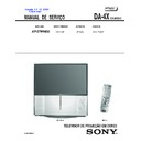
Sony KP-57WV600 / KP-57WV700 / KP-65WV600 / KP-65WV700 (serv.man5) Service Manual ▷ View online
COLOR REAR VIDEO PROJECTOR
SERVICE MANUAL
DA-4X
CHASSIS
KP-57WV600
RM-Y188 US/CND
SCC-P92D-A
KP-57WV700
RM-Y188 US/CND
SCC-P92B-A
KP-65WV600
RM-Y188 US/CND
SCC-P92C-A
KP-65WV700
RM-Y188 US/CND
SCC-P92A-A
MODEL NAME
REMOTE COMMANDER
DESTINATION
CHASSIS NO.
CORRECTION - 3
SUBJECT: CONVERGENCE ADJUSTMENT PROCEDURE
Correct the service manual as shown.
File this Correction with the service manual.
9-965-926-93
☛
: Corrected Item
Section 2: Set Up Adjustments
2-12 Registration Adjustment (PJE Mode Only) (Page 48)
2-13-2 Copying All Registration Data to Other Modes (Page 52)
Sony Corporation
Sony Technology Center
Technical Services
Service Promotion Department
English
2003AJ74WEB-1
Printed in USA
© 2003.1
—
48 —
KP-57WV600/57WV700/
65WV600/65WV700
2-12. REGISTRATION ADJUSTMENT
(PJE MODE ONLY)
Change the
wide screen
mode
wide screen
mode
* When the
NTSC Full mode
adjustment has finished,
copy its data to
the zoom and
HD full modes
the first time only
and be sure to
adjust in the order given.
See 2-13-2 (p. 52)
adjustment has finished,
copy its data to
the zoom and
HD full modes
the first time only
and be sure to
adjust in the order given.
See 2-13-2 (p. 52)
*ADJUSTING FLOW
START
Turn on the power and wait for 10 minutes.
Set to the NTSC Full mode
Check the deflection yokes, the centering magnets,
2 pole/4 pole magnets
Set to the service mode.
MAIN DEFLECTION ADJUSTMENT (Green)
Green coarse adjustment
Green fine adjustment
Red coarse adjustment
Red fine adjustment
Blue fine adjustment
Blue coarse adjustment
Memorize the FLASH FOCUS offset data
(Run flash focus in Service Mode)
End
Another wide screen mode?
DEFLECTION
SUB
ADJUSTMENT
COPY*
Yes
No
2-12-1.SETUP FOR ADJUSTMENT
MARKING
• At the 4 sides of the screen, locate the middle. Use a tape measure
to identify the middle.
: middle
DATA SETTING
1. Set NTSC Full mode.
2. Enter the service mode, and select “PJE”.
NOTE: When you replace printed circuit boards or devices or CRTs, and
when correction is drastically necessary, press the “7” + ENTER on the
remote commander to initialize the data in the Projector Engine mode.
Press the MUTING + ENTER on the remote commander to write the
data.
when correction is drastically necessary, press the “7” + ENTER on the
remote commander to initialize the data in the Projector Engine mode.
Press the MUTING + ENTER on the remote commander to write the
data.
2-12-2.MAIN DEFLECTION ADJUSTMENT
NOTE: Before this adjustment, refer to section 2-11 for PJE item #78-85
input data.
input data.
1. Cover the red and blue CRT lenses with lens caps to allow only green
to show (or use the method shown in the note below for turning off the
CRTs individually without using lens caps).
CRTs individually without using lens caps).
2. Enter the monoscope signal and set to NTSC Full mode.
3. Enter the service mode, and select “2170D-1”.
4. Adjust “0 VPOS” and “1 VSIZ” so that the picture is displayed in the
center of the screen.
5. Adjust “2VSZ0” for 1080i vertical size adjustment.
0 VPOS
1 V-Size
6. Select “2170D-2” and adjust “2 H-Size” so that the picture size is
within the specifi cation.
2 H-Size
SPEC
Overscan Spec. = 9%
Input Signal
H SIZE
V SIZE
Monoscope
15.6 ± 0.2 sq.
11.5 ± 0.2 sq.
7. Copy the data of the NTSC Full mode to the other wide screen mode
and, if necessary, adjust in the other mode.
☛
—
52—
KP-57WV600/57WV700/
65WV600/65WV700
12. Select “GRN PIN”, and adjust so that right and left vertical lines on the
screen become straight. Adjust so that upper and lower horizontal lines
on the screen become straight.
on the screen become straight.
GRN PIN (Horizontally/Vertically)
Push the joystick
to
Push the joystick
to
Push the joystick
to
Push the joystick
to
13. Select “GRN KEY”, and adjust so that upper and lower horizontal lines
on the screen become parallel.
GRN KEY (Vertically)
Push the joystick
to
Push the joystick
to
Note: The VPIN and KEY adjustments affect each other.
If necessary, adjust these mutually.
14. Press the “9” button on the remote commander to enter fi ne adjustment
mode.
15. Make the fi ne adjustment so that horizontal lines and vertical lines
become straight.
16. Press the “9” button on the remote commander to return to coarse
adjustment mode.
2) RED ADJUSTMENT
1. Cover the blue CRT lens with a lens caps to allow only the green and red
to show (or use the method shown in the note below for turning off the
CRTs individually without using lens caps).
CRTs individually without using lens caps).
2. Press the “3” button on the remote commander to select RED mode.
3. Adjust the following items so that red lines overlap with green lines.
•
RED CENT (horizontally/vertically)
•
RED SKEW (horizontally/vertically)
•
RED SIZE (horizontally/vertically)
•
RED LIN (horizontally/vertically)
•
RED MSIZ (horizontally)
•
RED MLIN (horizontally)
•
RED PIN (horizontally/vertically)
•
RED KEY (vertically)
4. Press the “9” button on the remote commander to enter fi ne adjustment
mode.
5. Make the fi ne adjustment so that horizontal lines and vertical lines
overlap with green lines.
6. Press the “9” button on the remote commander to return to coarse
adjustment mode.
Note: If lens caps are unavailable, you can cut off the unnecessary color
beams by controlling the service mode 2170P-2 1 RGBS.
beams by controlling the service mode 2170P-2 1 RGBS.
3) BLUE ADJUSTMENT
1. Remove the lens cap from the blue picture lens to display all colors.
2. Press the “3” button on the remote commander to select BLU mode.
3. Adjust the following items so that blue lines overlap with green lines.
•
BLU CENT (horizontally/vertically)
•
BLU SKEW (horizontally/vertically)
•
BLU SIZE (horizontally/vertically)
•
BLU LIN (horizontally/vertically)
•
BLU PIN (horizontally/vertically)
•
BLU KEY (vertically)
4. Press the “9” button on the remote commander to enter fi ne
adjustment mode.
5. Make the fi ne adjustment so that horizontal lines and vertical lines
overlap with green and red lines.
6. Press the “9” button on the remote commander to return `to coarse
adjustment mode.
Note: When replacing CRTs, adjust the set-up adjustments (2-1 to 2-9)
and the registration adjustment (2-12). When replacing multiple CRTs at
the same time, replace and adjust them individually.
and the registration adjustment (2-12). When replacing multiple CRTs at
the same time, replace and adjust them individually.
4) REGISTRATION DATA WRITING
1. After completing each adjustment of green, blue, and red for the NTSC
Full mode press the “MUTING”+ “ENTER” buttons on the remote
commander to write the registration data to the NVM.
commander to write the registration data to the NVM.
2-13-2.COPYING ALL REGISTRATION DATA
TO OTHER MODES
1. Make sure that the adjustment for NTSC Full mode are complete and
the data have already been written.
2. Select the PJE mode.
3. Select COPY and set the data to “01”, and press the
“MUTING”+“ENTER” buttons on the remote commander.
4. The data from the NTSC Full mode is copied to zoom and HD full
modes.
Full
Screen
mode
Zoom
Screen
mode
HD
(1080i Full
Screen mode)
Copy Registration Data
5. Check in the other modes and adjust as demands.
Be sure to write data in each mode.
Adjustment for wide zoom mode should be done separately.
☛
Display


