DOWNLOAD Sony DCR-TRV130 / DCR-TRV130E / DCR-TRV230 / DCR-TRV230E / DCR-TRV235E / DCR-TRV325E / DCR-TRV330 / DCR-TRV330E / DCR-TRV430E / DCR-TRV530 / DCR-TRV530E / DCR-TRV725E / DCR-TRV730 / DCR-TRV730E / DCR-TRV828 / DCR-TRV828E / DCR-TRV830 / DCR-TRV830E (serv.man3) Service Manual ↓ Size: 39.52 KB | Pages: 1 in PDF or view online for FREE

Model
DCR-TRV130 DCR-TRV130E DCR-TRV230 DCR-TRV230E DCR-TRV235E DCR-TRV325E DCR-TRV330 DCR-TRV330E DCR-TRV430E DCR-TRV530 DCR-TRV530E DCR-TRV725E DCR-TRV730 DCR-TRV730E DCR-TRV828 DCR-TRV828E DCR-TRV830 DCR-TRV830E (serv.man3)
Pages
1 Few pages! See other manuals at the bottom of the first or last page.
Size
39.52 KB
Type
PDF
Document
Service Manual
Brand
Device
Movie / 8 MM VIDEO ADJUSTMENT MANUAL IX
File
dcr-trv130-dcr-trv130e-dcr-trv230-dcr-trv230e-dcr-.pdf
Date

Sony DCR-TRV130 / DCR-TRV130E / DCR-TRV230 / DCR-TRV230E / DCR-TRV235E / DCR-TRV325E / DCR-TRV330 / DCR-TRV330E / DCR-TRV430E / DCR-TRV530 / DCR-TRV530E / DCR-TRV725E / DCR-TRV730 / DCR-TRV730E / DCR-TRV828 / DCR-TRV828E / DCR-TRV830 / DCR-TRV830E (serv.man3) Service Manual ▷ View online

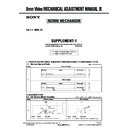
2)
Loosen the two screws (M1.7) of the LS cam plate and slide
the LS chassis block assembly to the drum side so as to
remove plate.
3)
Insert the thickness gauge 0.6 mm (Ref. No. J-15) between
the LS cam plate and the LS chassis block assembly. Push
the LS cam plate in the direction opposite to the drum to
remove plate.
Sony EMCS Co.
2007B1600-1
  ©2007.02
Published by Kohda TEC
9-929-861-92
CORRECTION-1
Correct your 8mm Video MECHANICAL ADJUSTMENT MANUAL IX as shown below.
Correction of check, adjustment and replacement
Ver. 1.3  2007. 02
Page
4. Check, Adjustment and Replacement
4-9. LS Cam Plate Position Adjustment (LS type A only)
 : Corrected portion
INCORRECT
CORRECT
22
8mm Video MECHANICAL ADJUSTMENT MANUAL IX
8mm Video MECHANICAL ADJUSTMENT MANUAL IX
M2000 MECHANISM
1. Adjustment Procedure
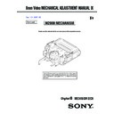
2)
Loosen the two screws (M1.7) of the LS cam plate and slide
the LS chassis block assembly to the drum side so as to
remove play.
3)
Insert the thickness gauge 0.6 mm (Ref. No. J-15) between
the LS cam plate and the LS chassis block assembly. Push
the LS cam plate in the direction opposite to the drum to
remove play.
1
 LS chassis
     block assembly
Push the LS chassis
block assembly
to remove play.
1
 LS chassis
     block assembly
Push the LS chassis
block assembly
to remove plate.
Display

Sony DCR-TRV130 / DCR-TRV130E / DCR-TRV230 / DCR-TRV230E / DCR-TRV235E / DCR-TRV325E / DCR-TRV330 / DCR-TRV330E / DCR-TRV430E / DCR-TRV530 / DCR-TRV530E / DCR-TRV725E / DCR-TRV730 / DCR-TRV730E / DCR-TRV828 / DCR-TRV828E / DCR-TRV830 / DCR-TRV830E (serv.man3) Service Manual ▷ Download

  • DOWNLOAD Sony DCR-TRV130 / DCR-TRV130E / DCR-TRV230 / DCR-TRV230E / DCR-TRV235E / DCR-TRV325E / DCR-TRV330 / DCR-TRV330E / DCR-TRV430E / DCR-TRV530 / DCR-TRV530E / DCR-TRV725E / DCR-TRV730 / DCR-TRV730E / DCR-TRV828 / DCR-TRV828E / DCR-TRV830 / DCR-TRV830E (serv.man3) Service Manual ↓ Size: 39.52 KB | Pages: 1 in PDF or view online for FREE
  • Here you can View online or download the Service Manual for the Sony DCR-TRV130 / DCR-TRV130E / DCR-TRV230 / DCR-TRV230E / DCR-TRV235E / DCR-TRV325E / DCR-TRV330 / DCR-TRV330E / DCR-TRV430E / DCR-TRV530 / DCR-TRV530E / DCR-TRV725E / DCR-TRV730 / DCR-TRV730E / DCR-TRV828 / DCR-TRV828E / DCR-TRV830 / DCR-TRV830E (serv.man3) in PDF for free, which will help you to disassemble, recover, fix and repair Sony DCR-TRV130 / DCR-TRV130E / DCR-TRV230 / DCR-TRV230E / DCR-TRV235E / DCR-TRV325E / DCR-TRV330 / DCR-TRV330E / DCR-TRV430E / DCR-TRV530 / DCR-TRV530E / DCR-TRV725E / DCR-TRV730 / DCR-TRV730E / DCR-TRV828 / DCR-TRV828E / DCR-TRV830 / DCR-TRV830E (serv.man3) Movie. Information contained in Sony DCR-TRV130 / DCR-TRV130E / DCR-TRV230 / DCR-TRV230E / DCR-TRV235E / DCR-TRV325E / DCR-TRV330 / DCR-TRV330E / DCR-TRV430E / DCR-TRV530 / DCR-TRV530E / DCR-TRV725E / DCR-TRV730 / DCR-TRV730E / DCR-TRV828 / DCR-TRV828E / DCR-TRV830 / DCR-TRV830E (serv.man3) Service Manual (repair manual) includes:
  • Disassembly, troubleshooting, maintenance, adjustment, installation and setup instructions.
  • Schematics, Circuit, Wiring and Block diagrams.
  • Printed wiring boards (PWB) and printed circuit boards (PCB).
  • Exploded View and Parts List.