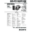
Sony DCR-PC115E / DCR-PC120E Service Manual ▷ View online
— 3 —
DCR-PC115E/PC120E
Checking supplied accessories.
Make sure that the following accessories are supplied with your camcorder.
Other accessories
3-070-988-11 MANUAL, INSTRUCTION (ENGLISH/RUSSIAN)
(PC115E/PC120E:UK)
3-070-988-21 MANUAL, INSTRUCTION (ITALIAN/GREECE) (PC115E)
3-070-988-31 MANUAL, INSTRUCTION (SPANISH/PORTUGUESE)
3-070-988-31 MANUAL, INSTRUCTION (SPANISH/PORTUGUESE)
(PC115E)
3-070-988-41 MANUAL, INSTRUCTION (FRENCH/GERMAN)
(PC120E:AEP)
3-070-988-51 MANUAL, INSTRUCTION (ENGLISH/DUTCH)
(PC120E:AEP)
3-071-132-11 OPERATING INSTRUCTION(NETWORK)
(ENGLISH/FRENCH)(PC120E)
3-071-132-21 OPERATING INSTRUCTION(NETWORK)
(GERMAN/DUTCH) (PC120E:AEP)
Note :
The components identified by mark
0
or dotted
line with mark
0
are critical for safety.
Replace only with part number specified.
Wireless Remote Commander (1)
RMT-811
1-475-950-21
RMT-811
1-475-950-21
AC power adaptor (1)
(AC-L10A)
(AC-L10A)
0
1-475-599-11
Size R6 (AA) battery for
Remote Commander (2)
(not supplied)
Remote Commander (2)
(not supplied)
A/V connecting cable (1.5m) (1)
1-765-080-11
1-765-080-11
21-pin adaptor (1)
1-573-291-11
1-573-291-11
Lens cap (1)
X-3949-944-1
X-3949-944-1
USB cable (1)
1-757-293-21
1-757-293-21
CD-ROM
(SPVD-004(P) USB Driver)(1)
3-066-676-01
(SPVD-004(P) USB Driver)(1)
3-066-676-01
Power cord (Main lead)(1) (AEP model)
0
1-769-608-11
Power cord (Main lead)(1) (UK model)
0
1-783-374-11
Battery terminal cover (1)
3-057-482-01
3-057-482-01
NP-FM50 battery pack (1)
(Not supplied)
(Not supplied)
Lens hood (1)
3-063-515-01
3-063-515-01
Memory stick (1)
MSA-8A
A-7024-735-A
MSA-8A
A-7024-735-A
Table for difference of functions
DCR-
Destination
NETWORK (Bluetooth)
Flash memory
(VC-270 board IC1406)
(VC-270 board IC1406)
SDRAM
(VC-270 board IC1404)
(VC-270 board IC1404)
BT-003 board
PC115E
AEP
✕
4Mbit
16Mbit
✕
PC120E
AEP, UK
a
32Mbit
64Mbit
a
Remarks
X301 of VC-270 board is 40.5MHz.
With BT-003 board
— 4 —
DCR-PC115E/PC120E
TABLE OF CONTENTS
SERVICE NOTE
1.
POWER SUPPLY DURING REPAIRS ····························· 5
2.
TO TAKE OUT A CASSETTE WHEN NOT EJECT
(FORCE EJECT) ································································ 5
(FORCE EJECT) ································································ 5
3.
DISCHARGING OF THE FLASHLIGHT POWER
SUPPLY CAPACITOR ······················································ 6
SUPPLY CAPACITOR ······················································ 6
3-1.
DISCHARGING THE CAPACITOR USING THE
SHORT JIG ········································································ 6
SHORT JIG ········································································ 6
3-1-1. PREPARING THE SHORT JIG ········································· 6
3-1-2. DISCHARGING THE CAPACITOR ································· 6
3-2.
3-1-2. DISCHARGING THE CAPACITOR ································· 6
3-2.
DISCHARGING THE CAPACITOR USING THE
REMOTE COMMANDER ················································ 6
REMOTE COMMANDER ················································ 6
3-2-1. DISCHARGING THE CAPACITOR ································· 6
3-2-2. PROCESSING AFTER COMPLETING REPAIRS/
3-2-2. PROCESSING AFTER COMPLETING REPAIRS/
ADJUSTMENTS ································································ 6
SELF-DIAGNOSIS FUNCTION
1.
SELF-DIAGNOSIS FUNCTION ······································· 7
2.
SELF-DIAGNOSIS DISPLAY ·········································· 7
3.
SERVICE MODE DISPLAY ············································· 7
3-1.
Display Method ·································································· 7
3-2.
Switching of Backup No. ··················································· 7
3-3.
End of Display ···································································· 7
4.
SELF-DIAGNOSIS CODE TABLE ··································· 8
1.
MAIN PARTS
1.
ORNAMENTAL PARTS ···················································· 9
2.
DISASSEMBLY ······························································· 10
2-1.
CABINET (L) SECTION ················································· 12
2-2.
VTR COMPLETE, CABINET (R) SECTION ················ 13
2-3.
FJ-035 BOARD ································································ 14
2-4.
VM-027 BOARD ····························································· 15
2-5.
CD-349P BOARD, LENS DEVICE ································ 15
2-6.
VC-270 BOARD ······························································ 16
2-7.
MECHANISM DECK ······················································ 16
2-8.
FLASH UNIT (MC) ························································· 17
2-9.
FLASH UNIT (ST) ·························································· 17
2-10. CABINET (G) BLOCK ASSEMBLY, ETC. ···················· 18
2-11. CONTROL SWITCH BLOCK (FK-1850) ······················ 19
2-12. CONTROL SWITCH BLOCK (PS-1850) ······················· 19
2-13. BLIND PLATE ASSEMBLY ··········································· 20
2-14. PD-148B BOARD, INVERTER TRANSFORMER UNIT · 20
2-15. HINGE ASSEMBLY ························································ 21
3.
REPAIR PARTS LIST ······················································ 22
3-1.
EXPLODED VIEWS ······················································· 22
3-1-1. OVERALL SECTION ······················································ 22
3-1-2. CABINET (L) SECTION ················································· 23
3-1-3. VTR OVERALL SECTION ············································· 24
3-1-4. LENS-EVF SECTION ····················································· 25
3-1-5. CABINET (R) SECTION-1 ············································· 26
3-1-6. CABINET (R) SECTION-2 ············································· 27
2.
GENERAL
Main Features ············································································· 28
Quick Start Guide ······································································· 28
Getting started
Quick Start Guide ······································································· 28
Getting started
Using this manual ··································································· 29
Checking supplied accessories ··············································· 29
Step 1 Preparing the power supply ········································· 30
Installing the battery pack ···················································· 30
Charging the battery pack ···················································· 30
Connecting to a wall socket ················································· 31
Step 2 Setting the date and time ············································· 31
Step 3 Inserting a cassette ······················································· 32
Recording – Basics
Recording a picture ································································· 32
Shooting backlit subjects – BACK LIGHT ···························· 35
Shooting in the dark – NightShot/Super NightShot ··············· 35
Self-timer recording ································································ 35
Checking the recording – END SEARCH / EDITSEARCH /
Rec Review ·········································································· 36
Playback – Basics
Playing back a tape ································································· 36
To display the screen indicators – Display function ··············· 36
Viewing the recording on TV ················································· 37
Viewing the recording on TV ················································· 37
Advanced Recording Operations
Recording a still image on a tape – Tape Photo recording ····· 38
Adjusting the white balance manually ···································· 39
Using the wide mode ······························································ 40
Using the fader function ························································· 40
Using special effects – Picture effect ······································ 41
Using special effects – Digital effect ······································ 41
Using the PROGRAM AE function ········································ 42
Adjusting the exposure manually ··········································· 43
Focusing manually ·································································· 43
Interval recording ···································································· 44
Frame by frame recording – Cut recording ···························· 44
Advanced Playback Operations
Playing back a tape with picture effects ································· 45
Playing back a tape with digital effects ·································· 45
Enlarging images recorded on tapes – Tape PB ZOOM ········· 45
Quickly locating a scene using the zero set memory function ····· 46
Searching the boundaries of recorded tape by title – Title search · 46
Searching a recording by date – Date search ·························· 47
Searching for a photo – Photo search/Photo scan ··················· 47
Editing
Dubbing a tape ········································································ 48
Dubbing only desired scenes – Digital program editing (on tapes) ·· 49
Using with analog video unit and your computer
– Signal convert function ····················································· 52
Recording video or TV programmes ······································ 53
Inserting a scene from a VCR – Insert editing ························ 54
Audio dubbing ········································································ 55
Superimposing a title ······························································ 56
Making your own titles ··························································· 57
Labelling a cassette ································································· 57
Customising Your Camcorder
Changing the menu settings ···················································· 58
“Memory Stick” Operations
Using a “Memory Stick” – introduction ································· 60
Recording still images on “Memory Stick”s
– Memory Photo recording ·················································· 63
Recording an image from a tape as a still image ···················· 65
Superimposing a still image in the “Memory Stick” on an
image – MEMORY MIX ····················································· 66
Recording moving pictures on “Memory Stick”s
– MPEG movie recording ···················································· 68
Recording a picture from a tape as a moving picture ············· 68
Recording edited pictures as a moving picture
– Digital program editing (on “Memory Stick”s) ················ 69
Copying still images from a tape – Photo save ······················· 70
Viewing a still image – Memory photo playback ··················· 71
Viewing a moving picture – MPEG movie playback ············· 72
Viewing images using computer ············································· 72
Copying the image recorded on “Memory Stick”s to tapes ···· 74
Enlarging still images recorded on “Memory Stick”s
– Memory PB ZOOM ·························································· 75
Playing back images in a continuous loop – SLIDE SHOW ····· 75
Preventing accidental erasure – Image protection ·················· 76
Deleting images ······································································ 76
Writing a print mark – PRINT MARK ··································· 76
Using the optional printer ······················································· 77
Using the Network function
Accessing the network ···························································· 77
Troubleshooting
Types of trouble and their solutions ········································ 78
Self-diagnosis display ····························································· 79
Warning indicators and messages ··········································· 79
Self-diagnosis display ····························································· 79
Warning indicators and messages ··········································· 79
Additional Information
Usable cassettes ······································································ 80
About the “InfoLITHIUM” battery pack ································ 81
About i.LINK ·········································································· 81
Using your camcorder abroad ················································· 82
Maintenance information and precautions ······························ 82
Quick Reference
Identifying the parts and controls ··········································· 84
— 5 —
DCR-PC115E/PC120E
SERVICE NOTE
1.
POWER SUPPLY DURING REPAIRS
In this unit, about 10 seconds after power is supplied to the battery terminal using the regulated power supply (8.4V), the power is shut off so
that the unit cannot operate.
This following two methods are available to prevent this. Take note of which to use during repairs.
that the unit cannot operate.
This following two methods are available to prevent this. Take note of which to use during repairs.
Method 1
Use the AC power adaptor (AC-L10, AC-VQ800, AC-SQ950 etc.).
Method 2
Connect the servicing remote commander RM-95 (J-6082-053-B) to the LANC jack, and set the commander switch to the “ADJ” side.
2.
TO TAKE OUT A CASSETTE WHEN NOT EJECT (FORCE EJECT)
1
Refer to 2-2. to remove the HS cover.
2
Refer to 2-2. to remove the jack cover.
3
Refer to 2-2. to remove the cabinet (R) assembly.
4
Refer to “3. DISCHARGING OF THE FLASHLIGHT POWER SUPPLY CAPACITOR” to discharge the flash power supply capacitor.
5
Refer to 2-3. to remove the mechanism deck and the lens block and the EVF block from the cabinet (L) block.
6
Disconnect CN302 (72P, 0.4mm) of VC-270 board.
7
Disconnect CN006 (27P, 0.3mm) of VC-270 board.
8
Supply +4.5V from the DC power supply to the loading motor and unload with a pressing the cassette compartment.
: Unloading
: Loading
VC-270 board
Loading motor
Regulated power supply
(+4.5Vdc)
CN006
CN302
— 6 —
DCR-PC115E/PC120E
3.
DISCHARGING OF THE FLASHLIGHT POWER SUPPLY CAPACITOR
The capacitor (C2010) of the flash unit (MC1850) is charged up to the maximum 300V potential. There is a danger of electric shock by this
high voltage when the flash unit (MC1850 or ST1850) is handled by hand. The electric shock is caused by the charged voltage which is kept
without discharging when the main power of the unit is simply turned off. Therefore, the remaining voltage must be discharged as described
below.
high voltage when the flash unit (MC1850 or ST1850) is handled by hand. The electric shock is caused by the charged voltage which is kept
without discharging when the main power of the unit is simply turned off. Therefore, the remaining voltage must be discharged as described
below.
3-1.
DISCHARGING THE CAPACITOR USING THE SHORT JIG
3-1-1.
PREPARING THE SHORT JIG
To preparing the short jig. a small clip is attached to each end of a resistor of 1k
Ω
/1W (1-215-869-11). Wrap insulating tape fully around the
reads of the resistor to prevent electric shock.
3-1-2.
DISCHARGING THE CAPACITOR
Connect the short jig with the capacitor directly.
1
1
Remove the power supply (Battery or AC power adaptor).
2
Short circuit between TP001 of the flash unit (MC1850) and the GND
(Chassis etc.) with the short jig about 10 seconds.
(Chassis etc.) with the short jig about 10 seconds.
3-2.
DISCHARGING THE CAPACITOR USING THE REMOTE COMMANDER
3-2-1.
DISCHARGING THE CAPACITOR
Note:
Perfect discharge can’t be done in this method. (Remaining voltage = Approx. 90V)
1
Connect the power supply (Battery or AC power adaptor).
2
Set POWER switch to “CAMERA”.
3
Connect the adjustment remote commander to the LANC jack, and set the HOLD switch to the “ADJ” side.
4
Select page: 0, address: 01. and set data: 01.
5
Select page: D, address: F4. set data: 04, and press PAUSE button of the adjustment remote commander.
6
Press FLASH ( ) button and set to the forced flash mode ( ), and press PHOTO button to pop up the flash.
7
Select page: 6, address: B3. and set data: 03.
8
Select page: 6, address: B1. and set data: 01.
9
Select page: 6, address: B0. and set data: 01.
→
The flash flashes, and data are returned to “00”
0
Repeat step 9, until the flash dose not flash.
After completing repairs/adjustments, perform “PROCESSING AFTER COMPLETING REPAIRS/ADJUSTMENTS”
After completing repairs/adjustments, perform “PROCESSING AFTER COMPLETING REPAIRS/ADJUSTMENTS”
3-2-2.
PROCESSING AFTER COMPLETING REPAIRS/ADJUSTMENTS
1
Connect the power supply (Battery or AC power adaptor).
2
Set POWER switch to “CAMERA”.
3
Connect the adjustment remote commander to the LANC jack, and set the HOLD switch to the “ADJ” side.
4
Select page: 0, address: 01. and set data: 01.
5
Select page: D, address: F4. set data: 00, and press PAUSE button of the adjustment remote commander.
6
Select page: 6, address: B3. and set data: 00.
7
Select page: 6, address: B1. and set data: 00.
8
Select page: 0, address: 01. and set data: 00.
1 k
Ω
/1 W
Wrap insulating tape
Flash unit
(MC1850) TP001
(MC1850) TP001
Flash unit (MC1850)
C2010
Short jig
GND
Chassis
(Sheet metal bending block)
Chassis
(Sheet metal bending block)
1 k
Ω
/1 W resistor
(1-215-869-11)

