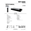
Sony BDP-A6000 Service Manual ▷ View online
9-4
BDP-A6000
Audio section flowchart
Audio does not sound right
No
Video is output properly
No
To Video section flowchart
Yes
Is the drive operating properly?
No
To Drive flowchart
Yes
Is each power supply supplied to the AUDIO
Block?
Block?
No
To Power Supply (System) flowchart
Yes
Only Analog 2ch L/R Audio affected?
No
Only Digital Audio (HDMI, Coax)
affected?
affected?
No
Replace the MB board
Yes
Yes
Yes
Is there HDMI output?
No
Replace the MB board
Is there Coaxial output?
Is there audio system digital signal input to
IC901?
IC901 pin1: A RO_R
IC901 pin10:ALO_R
IC901?
IC901 pin1: A RO_R
IC901 pin10:ALO_R
No
Replace the MB board
Yes
Are control signals input to IC901?
IC901pin7: MUTE
No
Replace the MB board
Yes
Is there a problem with mount condition of
IC901
IC901
No
Replace IC901 or replace MB board
Check output resistor/capasitors
(R911,R918,C910,C918)
(R911,R918,C910,C918)
No
IC 305 Pin 5: SW3.3V
9-5
BDP-A6000
FR-317 IF board flow chart
Does symptom improve when replace
FR-317
board?
Reconnect FFC, if symtoms
donot improve, replace
FFC
donot improve, replace
FFC
Does FFC disconnected
CN702
or broken
from
Yes
No
Is there voltage of about 3.3V at pin
5,6
of
CN201
without pressin
g
the ke
y
s?
Check IC1302 (MB board)
Yes
Check the potential voltage CN201
pin5,6 change from +3.3V to near 0V
when pressing the power button.
pin5,6 change from +3.3V to near 0V
when pressing the power button.
Disconnected FFC or
TS-160
board
replace
Reconnect FFC, if symtoms
do not improve, replace
FFC
do not improve, replace
FFC
Does harness disconnected
CN201
or broken
from
Yes
No
Check pattern and IC201 might be broken
Yes
POWER does not operate
No
No
No
CHECK IC1302(MB board)
TS-160 board
Video section flowchart
Reproduced video does not appear right
Is the FL display/LED display correct?
No
To Main flowchart
Is the drive operating properly?
No
To Drive flowchart
Check the input power
No
IC101 pin V22 & T27 : 3.3V
Is a video signal output from
IC101
?
No
Check the writing from IC101
To Power (System) flowchart
Pin U27 : VDACX_OUT
Yes
Yes
Yes
Yes
9-6
BDP-A6000
No
No
No
No
No
No
Yes
Yes
No
Yes
Yes
Yes
Yes
Yes
No
Yes
No
No
Yes
No
Yes
No
Yes
No
Yes
TS-161 Board Flowchart
No
Yes
Yes
9-7
BDP-A6000
Remote control does not operate
Check of +3.3V voltage at IC701 pin1?
No
(MB board)
No
To Power supply flow chart
Yes
No
Check FFC disconnected from
CN702 or broken?
CN702 or broken?
Yes
Check of appearance waveform during
pressing remote control at IC701 pin2
pressing remote control at IC701 pin2
No
Yes
Check of +3.3V voltage at CN1305 pin 2?
Check of +3.3V voltage at CN702 pin 2?
No
Replace FFC
If symptoms do not improve,
Change FR board
If symptoms do not improve,
Change FR board
Check of appearance waveform during
pressing remote control at CN1305
pin1 (MB board)
pressing remote control at CN1305
pin1 (MB board)
Yes
Yes
Change FR Board
No
Check of appearance waveform
during pressing remote control
at CN702 pin1
during pressing remote control
at CN702 pin1
No
Replace IC701
If symptoms do not improve,
Change FR board
If symptoms do not improve,
Change FR board
Check pattern along SIRCS line
If symptom do not improve,
Change FR board
If symptom do not improve,
Change FR board
Check FFC disconnected from
CN702 or broken?
CN702 or broken?
No
Reconnect
FFC
If symptoms do not improve,
Change FFC
Change FFC
Yes
Yes
Change FR Board
Yes
Check pattern around IC701
If symptom do not improve,
Change FR board
If symptom do not improve,
Change FR board
CHECK IC1302 (MB board)
Click on the first or last page to see other BDP-A6000 service manuals if exist.

