Sony DSC-W30 / DSC-W40 (serv.man10) Service Manual ▷ View online
SERVICE MANUAL
LEVEL
3
Ver. 1.3 2007.06
Sony EMCS Co.
9-876-935-88
2007F0500-1
© 2007.6
Published by Kohda TEC
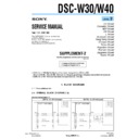
SUPPLEMENT-2
File this supplement with the service manual.
(DI07-023)
• Change of Repair Parts
DSC-W30/W40
US Model
Canadian Model
AEP Model
UK Model
E Model
Australian Model
Hong Kong Model
Chinese Model
Korea Model
Argentine Model
Brazilian Model
Japanese Model
Tourist Model
DSC-W30/W40_L3
Former
New
4.2
4.1
4
0
2A/32V
F001
FDW2508P/GNL
Q002
1
4
2
3
3
8
6
7
2A/32V
F002
SWITCH
4.2
4.1
4
0
FDW2508P/GNL
Q002
1
4
2
3
3
8
6
7
2A/32V
F002
SWITCH
1.25A/32V
F001
4. PRINTED WIRING BOARDS AND SCHEMATIC DIAGRAMS
4-2. SCHEMATIC DIAGRAMS
: Points changed portion.
SY-143 BOARD (7/7) (DC/DC CONVERTER)
(Service manual page 4-12, Location A-4 to B-7)
The components identified by
mark 0 or dotted line with
mark 0 are critical for safety.
Replace only with part number
specified.
mark 0 or dotted line with
mark 0 are critical for safety.
Replace only with part number
specified.
Les composants identifiés par une
marque 0 sont critiques pour la
sécurité.
Ne les remplacer que par une pièce
portant le numéro spécifié.
marque 0 sont critiques pour la
sécurité.
Ne les remplacer que par une pièce
portant le numéro spécifié.
— 2 —
DSC-W30/W40_L3
5-2. ELECTRICAL PARTS LIST
Page
Former
New
Ref. No.
Part No.
Description
Ref. No.
Part No.
Description
5-10
A-1176-182-A SY-143 BOARD, COMPLETE (SERVICE)
(W30: GP1)
A-1176-183-A SY-143 BOARD, COMPLETE (SERVICE)
(W30: GP4/W40: GP4)
A-1176-184-A SY-143 BOARD, COMPLETE (SERVICE)
(W30: GP2/W40: GP2)
A-1176-185-A SY-143 BOARD, COMPLETE (SERVICE)
(W30: GP3/W40: GP3)
**********************
< CONNECTOR >
* CN901 1-817-564-51 CONNECTOR, FPC (ZIF) 33P
< FUSE >
0 F001
1-576-851-21 FUSE (2A/32V)
< IC >
* IC101
8-753-251-12 IC CXD3199GG-T6
IC301
6-708-961-01 IC VSP00M20ZWDR
< COIL >
L005
1-456-992-11 INDUCTOR
4.7uH (Note 2)
L006
1-456-992-11 INDUCTOR
4.7uH (Note 2)
L007
1-456-992-11 INDUCTOR
4.7uH (Note 2)
L009
1-456-992-11 INDUCTOR
4.7uH (Note 2)
< RESISTOR >
R108
1-208-679-11 METAL CHIP
680
0.5%
1/16W
< VIBRATOR >
* X101
1-813-403-21 QUARTZ CRYSTAL OSCILLATOR (12MHz)
A-1176-182-A SY-143 BOARD, COMPLETE (SERVICE)
(W30: GP1)
A-1176-183-A SY-143 BOARD, COMPLETE (SERVICE)
(W30: GP4/W40: GP4)
A-1176-184-A SY-143 BOARD, COMPLETE (SERVICE)
(W30: GP2/W40: GP2)
A-1176-185-A SY-143 BOARD, COMPLETE (SERVICE)
(W30: GP3/W40: GP3)
**********************
< CONNECTOR >
* CN901 1-817-564-71 CONNECTOR, FPC (ZIF) 33P
< FUSE >
0 F001
1-576-513-11 FUSE, MICRO (1608) (1.25A/32V)
(Note 1)
< IC >
IC101
8-753-239-15 IC CXD3188AGG-T6
* IC301
6-710-471-01 IC VSP00M21ZWDR-9
< COIL >
L005
1-456-995-22 INDUCTOR
4.7uH
L006
1-456-995-22 INDUCTOR
4.7uH
L007
1-456-995-22 INDUCTOR
4.7uH
L009
1-456-995-22 INDUCTOR
4.7uH
< RESISTOR >
R108
1-208-883-81 METAL CHIP
680
0.5%
1/16W
< VIBRATOR >
X101
1-813-403-41 QUARTZ CRYSTAL OSCILLATOR (12MHz)
5. REPAIR PARTS LIST
5-9
The components identified by
mark 0 or dotted line with
mark 0 are critical for safety.
Replace only with part number
specified.
mark 0 or dotted line with
mark 0 are critical for safety.
Replace only with part number
specified.
Les composants identifiés par une
marque 0 sont critiques pour la
sécurité.
Ne les remplacer que par une pièce
portant le numéro spécifié.
marque 0 sont critiques pour la
sécurité.
Ne les remplacer que par une pièce
portant le numéro spécifié.
5-11
Note 2: These parts have been changed in the supplement-1 (9-876-935-83).
Note 1: The rating may be different from that given on the
printed wiring board.
Use new type part when replacing the F001.
Use new type part when replacing the F001.
Display

