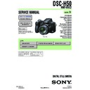
Sony DSC-H5 (serv.man9) Service Manual ▷ View online
Sony EMCS Co.
2006F1600-1
©2006.06
Published by Kohda TEC
9-852-117-92
SERVICE MANUAL
CORRECTION-1
Correct your service manual as shown below.
• Correction of service note
• Correction of block diagrams
• Correction of schematic diagrams
• Correction of printed wiring boards
• Correction of electrical parts list
• Correction of block diagrams
• Correction of schematic diagrams
• Correction of printed wiring boards
• Correction of electrical parts list
Ver. 1.1 2006. 06
DSC-H5_L2
US Model
Canadian Model
AEP Model
UK Model
E Model
Australian Model
Chinese Model
Brazilian Model
Hong Kong Model
Korea Model
Tourist Model
Japanese Model
LEVEL
2
DSC-H5
— 2 —
DSC-H5_L2
Page
1. SERVICE NOTE
1-5. INITIAL LANGUAGE DATA CHECK
: Added portion
INCORRECT
1-3E
Page
3. BLOCK DIAGRAMS
: Corrected portion
INCORRECT
CORRECT
3-1
Initial Language Data
Page
Address
Data
Language
GP1
GP2
GP3
GP4
4F
8C
00
English
z
z
z
01
Japanese
z
04
Spanish
z
z
08
Simplified Chinese
z
0B
Russian
z
0D
Korean
z
Note: GP1 is fixed to Japanese.
GP2 is fixed to English.
GP3 is either English, Spanish, or Russian.
GP4 is either English, Spanish, Simplified Chinese, or Korean.
GP3 is either English, Spanish, or Russian.
GP4 is either English, Spanish, Simplified Chinese, or Korean.
CORRECT
Initial Language Data
Page
Address
Data
Language
GP1
GP2
GP3
GP4
4F
8C
00
English
z
z
z
01
Japanese
z
04
Spanish
z
z
06
Portugal
08
Simplified Chinese
z
z
0B
Russian
z
0D
Korean
z
Note: GP1 is fixed to Japanese.
GP2 is fixed to English.
GP3 is either English, Spanish, or Russian.
GP4 is either English, Spanish, Portugal, Simplified Chinese, or Korean.
GP3 is either English, Spanish, or Russian.
GP4 is either English, Spanish, Portugal, Simplified Chinese, or Korean.
IC002
CCD IMAGER
15
23
24
20
20
1
1
H1A,B
H2A,B
RG
H2A,B
RG
V1
V2
V3A,B
V4
V5A,B
V6
V2
V3A,B
V4
V5A,B
V6
1-14
27,28
19-17
19-17
IC001
BUFFER
3
1
C
V
VSUB
Q001
R
CD-617 BOARD
CD-621 FLEXIBLE
BOARD
BOARD
4
4
V7
V8
V9
V10
VST,
VHLD
V8
V9
V10
VST,
VHLD
IC002
CCD IMAGER
15
23
24
20
20
1
1
H1A,B
H2A,B
RG
H2A,B
RG
CSUB
V1
V2
V3A,B
V4
V5A,B
V6
V2
V3A,B
V4
V5A,B
V6
1-14
27,28
19-17
19-17
IC001
BUFFER
3
1
C
V
VSUB
Q001
R
CD-617 BOARD
CD-621 FLEXIBLE
BOARD
BOARD
4
4
V7
V8
V9
V10
VST,
VHLD
V8
V9
V10
VST,
VHLD
3-1. OVERALL BLOCK DIAGRAM (1/2)
IC506
G5
J5
PITCH AD
YAW AD
D5
D6
C_RESET
PITCH
SENSOR
YAW
SENSOR
SE501
SE502
MUTE
PITCH/YAW
SENSOR
AMP
8
12
2
18
19
14
6
Q503
(6/8)
IC506
G5
J5
PITCH AD
YAW AD
D5
D6
C_RESET
PITCH
SENSOR
YAW
SENSOR
SE501
SE502
BUFFER
PITCH/YAW
SENSOR
AMP
8
12
2
18
19
14
6
Q503
(6/8)
— 3 —
DSC-H5_L2
Page
: Corrected portion
INCORRECT
CORRECT
3-2
3-2. OVERALL BLOCK DIAGRAM (2/2)
705
CN201
AF-105 FLEXIBLE BOARD
PL-045 BOARD
D001 (AF LED)
STRB PLUNGER
XSTRB_POPUP
XAF LED
S001
(LENS COVER OPEN)
S201
(FLASH POP UP)
RY201
PLUNGER
1
4
5
8
7
7
6
4
3
3
705
CN201
AF-105 FLEXIBLE BOARD
PL-045 BOARD
D001 (AF LED)
STRB PLUNGER
XSTRB_POPUP
XAF LED
S001
(LENS COVER OPEN)
S201
(FLASH POP UP)
RY201
PLUNGER
1
4
5
8
7
7
6
4
3
3
1
3
4
4
3-4. POWER BLOCK DIAGRAM (2/2)
3-4E
IC504
STEADY SHOT
CONTROL
(6/8)
1.5V
3
89
IC505
1.5V REG
(6/8)
4
1
IC504
STEADY SHOT
CONTROL
(6/8)
1.5V
3
B9
IC505
1.5V REG
(6/8)
4
1
Page
INCORRECT
CORRECT
4-11
AF-105 FLEXIBLE BOARD
4. PRINTED WIRING BOARDS AND SCHEMATIC DIAGRAMS
4-2. SCHEMATIC DIAGRAMS
Note: D001 is not included in this
COMPLETE of AF-105 board.
COMPLETE of AF-105 board.
Note: D001 (AF LED) is not supplied,
but this is included in AF-105
flexible board complete.
Page
INCORRECT
CORRECT
4-27
PL-045 BOARD (SIDE A)
4-3. PRINTED WIRING BOARDS
: Corrected portion
: Added portion
Note: RY201 is not included in this
COMPLETE of PL-045 board.
AF-105 FLEXIBLE BOARD
Note: D001 (AF LED) is not supplied,
but this is included in AF-105
flexible board complete.
— 4 —
DSC-H5_L2
Page
A-1176-913-A AF-105 FLEXIBLE BOARD, COMPLETE
******************************
(D001 (AF LED) is not supplied, but this is included
in AF-105 flexible board complete.)
< DIODE >
D001
Not supplied
DIODE DOR5073 (AF LED)
(D001 (AF LED) is not supplied, but this is included
in AF-105 flexible board complete.)
A-1176-913-A AF-105 FLEXIBLE BOARD, COMPLETE
******************************
(D001 is not included in this COMPLETE board.)
< DIODE >
D001
Not supplied
DIODE DOR5073 (AF LED)
(D001 is not included in this COMPLETE of
AF-105 board.)
Ref. No.
Part No.
Description
Ref. No.
Part No.
Description
5. REPAIR PARTS LIST
5-2. ELECTRICAL PARTS LIST
: Corrected portion
INCORRECT
CORRECT
5-10
Be sure to read “Precautions upon replacing CCD
imager” on page 4-1 when changing the CCD imager.
imager” on page 4-1 when changing the CCD imager.
Be sure to read “Precautions upon replacing CCD
imager” on page 4-3 when changing the CCD imager.
imager” on page 4-3 when changing the CCD imager.
Display

